First step toward turbo
Printed From: West Coast Fieros
Category: General Fiero Chat
Forum Name: General Talk about Fieros
Forum Description: Just want to chat about fieros? here's the place to make that happen.
URL: http://www.westcoastfieros.com/forum/forum_posts.asp?TID=1625
Printed Date: 02 August 2025 at 6:56pm
Software Version: Web Wiz Forums 12.01 - http://www.webwizforums.com
Topic: First step toward turbo
Posted By: CFoss
Subject: First step toward turbo
Date Posted: 02 December 2009 at 10:29am
|
Hey all. I'm kinda excited today. Hopefully I didn't make a mistake, but who knows.
I've been looking at turbos for my 3.4 for a while now. Ebay chinese t3/t4 50 trim/.63 ar models look good, but there is way too much bad karma out there to buy a $200 turbo and slap it on and call it good. Plus, they don't have water cooled center sections, and I'm bad at changing oil, so coking would be a concern.
The good t3/t4s from turbonetics/garrett cost $1000, which is what I have planned for the whole deal.
So, I researched MHI (Mitsubishi) turbos and decided that a TD05HR-16G6-9T would fit well. The map is very much the same as the 50trim T4, and the 9CM2 turbine is like a A/R of .65, a touch bigger than most .63t3 people are using...cost??? 365CDN delivered. Hopefully it's as advertised!
Chay ------------- 86 SE 3.4 |
Replies:
Posted By: Capt Fiero
Date Posted: 02 December 2009 at 11:54am
|
Congrats. ------------- Capt Fiero 88 Fiero GT 5spd V6 Eight Fifty Seven GT V8 5spd. |
Posted By: Dr.Fiero
Date Posted: 02 December 2009 at 5:32pm
|
I had the best results on mine when I had a simple rising rate FPR (1lb boost = 1lb rise in fuel pressure), and a mallory 685 box doing boost retard through a second separate 2bar MAP. It was simple. It was uncool'ish. IT WORKED! Then I started to get fancy with redoing all my timing tables, fuel tables.... bla bla bla.... I got slower. :( KISS principle frequently works. For me it did. |
Posted By: CFoss
Date Posted: 06 December 2009 at 8:12pm
|
Did you ever figure out why...was it because you were leaner with the fpr? Did you get slower because you were more conservative with the tune on the timing side? How much did the fpr andf mallory box cost? I'm wondering because I'd like to go to the '7730, so I'd be tuning anyway. Seems like it would be ok, but not optimal in all conditions because the boost could be on with part throttle in which case you'd either be lean with full throttle, or rich with part throttle. How the heck does the thing work? Chay ------------- 86 SE 3.4 |
Posted By: Dr.Fiero
Date Posted: 07 December 2009 at 7:01am
|
Never did figure out why. As for part/full throttle, remember that neither system cares where your foot is (the TPS only reports the 'change or rate of change' in throttle to the ECM, it really doesnt care what the actual position is) - the AFR and timing is based solely on RPM and MAP readings. Is that what you meant by "the thing", or was there a different 'thing'?  |
Posted By: CFoss
Date Posted: 07 December 2009 at 10:06am
|
You're an english teacher too. Ok, sorry for the vague pronoun. The thing was the fpr, but I meant from a systems point of view...how does it integrate. I understand it boosts fuel pressure for manifold pressure increases, no big surpise there, it delivers more fuel. I get what you mean by the afr and rpm. What I mean is that to fully deterine flow you need map, rpm and iat. With only a map signal, the fpr could be fueling too much or not enough, so it's kinda like a fudger, or good enough. Am I getting that right? I guess given that the AFR can be between 12.5-13.5 on boost it's not a huge deal. What was the cost, do you remember??
Thanks,
C ------------- 86 SE 3.4 |
Posted By: Dr.Fiero
Date Posted: 07 December 2009 at 11:33am
|
Yep - that's about it! "Close enough" is frequently good enough. ;) Sure, if you can nail down your fuel table perfectly, you WILL go faster (as proved by some of the fastest street car shootouts). The trick is.. getting it spot on. Something I could never quite nail down. Oh, the IAT does come into play for accuracy (especially in a turbo setup where you can go from OAT to 300F in a matter of seconds!), but isn't a total requirement. A lot of the TBI setups from the factory don't even use it. I added (moved really) my IAT probe over to the far side of my upper intake plenum. Figured there's no point in measuring the air temp over at the filter! |
Posted By: CFoss
Date Posted: 07 December 2009 at 11:49am
|
Understood. I will move my iat to the area preceeding the throttle body somewhere. It's advised to use a open type for the turbo too, because they respond better (Quicker) to rapidly changing intake temps.
I looked at the density change from 0 to 200 deg F. It's not really that much, like 23% for that massive range, so I can see why it's not used sometimes ((0+460)/200+460)). I was kinda blown away how little it changed actually. I bet the 02 sensor can make up for it in most cases, then at wot it's not used anyway. when it's cold it's hard to detonate, so the lean mix doesn't really hurt you. It all makes some kind of sense.
I'll check into it. I'm still kind of curious to see if I'm up to the challenge of tuning it. I'm looking to trying the process after reading so much material.
Chay ------------- 86 SE 3.4 |
Posted By: CFoss
Date Posted: 07 December 2009 at 11:52am
|
One more thing...looks like I got boned on the turbo.
I saw some compressor maps which looked good, rated in CFM and I bought it....but they are crap. I should have known. When I got the real maps, rated in KG/second, the turbo compressor is a bit small. The turbine should be ok. Crap. I'm going to try it anyway, but I don't expect much in the higher rpm ranges(4500 and up). Oh well, it's a street car and I don't like going that fast anyway, maybe it will suit me. I'm just going to have to watch the iat's when I first go at it.
Chay ------------- 86 SE 3.4 |
Posted By: Dr.Fiero
Date Posted: 07 December 2009 at 2:30pm
|
I simply drilled another hole in the end if the plenum, right beside the power brake hose. My (88) manifold had an extra boss/drill pad right there! Tapped out to (3/8?) NPT, installed sensor, lengthened wires, done.
|
 CFoss wrote:
Posted By: CFoss
Date Posted: 07 December 2009 at 3:14pm
|
Not a half bad idea. It would get it away from a congested area too.
I like.
C ------------- 86 SE 3.4 |
Posted By: Patrick
Date Posted: 07 December 2009 at 6:32pm
|
A related question... At what air temperature reading from the IAT (MAT sensor) does the ECM no longer richen the mixture for "cold" weather driving? And can that be artificially induced by grounding or shorting the IAT? You can probably see where I'm going with this. After the engine has been running for a few minutes, I'd like to fool the ECM into thinking it's a hot day and the engine is all warmed up to see if gas mileage can be improved. [EDIT] After posting I came across http://www.gmtips.com/3rd-degree/dox/tips/mat/mat.htm - this interesting article about relocating the MAT sensor. That article is one of many informative tips to be found http://gmtips.com/3rd-degree/dox/tips/tips.htm - Here .
|
Posted By: CFoss
Date Posted: 08 December 2009 at 11:29am
|
I'm not sure abot the ecm programming, but the iat can read temps down to -40.
Unless, of course, you run open loop, but that's another story. Opinions? Chay ------------- 86 SE 3.4 |
Posted By: Dr.Fiero
Date Posted: 08 December 2009 at 12:06pm
|
If you 'tell' the ECM that you're at -40 for more than 60 seconds (?) you'll also set an error flag (CEL). Of course, you're trying to go the other way around - just don't exceed something like 220 for too long or you'll set an error again. You could also just switch to megasquirt and a wideband, and eliminate all the antiquated tuning problems. ;) |
Posted By: wayneh70
Date Posted: 09 December 2009 at 11:02pm
I found a great http://cgi.ebay.com/ebaymotors/Pontiac-Bonneville-Fiero-Turbo-Simulator-94-98-00-02-04_W0QQitemZ230410128549QQcmdZViewItemQQptZMotors_Car_Truck_Parts_Accessories?hash=item35a5838ca5 - item on Ebay that bypasses the whole pesky ECM/fuel table mess, I'm going to get one for my Fiero! (when I get a Fiero...soon now  ) )Good for a chuckle anyway... |
Posted By: CFoss
Date Posted: 10 December 2009 at 9:55am
|
"Will the turbo simulator require cleaning or maintenance?
Now that's some funny !hit.
C ------------- 86 SE 3.4 |
Posted By: Romeo
Date Posted: 11 December 2009 at 1:09pm
|
Hey, what would you guys do in the case of extreme ram-air induction? As the ECU would have to self-correct not on a trip-by-trip basis, but by speed. ------------- Never shift into reverse without a back-up plan. |
Posted By: Capt Fiero
Date Posted: 11 December 2009 at 8:21pm
|
I don't care what kind of ram air you are never going to get over 1psi boost in your intake plenum without a mechanical device to raise the boost. At best my holly scoop takes me from a negative pressure in the plenum to near zero when I am at a 130mph cruise. If you by some crazy way, all you would need to cheat the system is a rising rate fuel pressure reg, and a check valve so the 1 bar map did not see boost. With the minor amount of extra air the car would be fine. The rising rate fpr would actually not even be needed until you found a way to make more than 2lbs of boost which is a LOT for a ram air system, if achievable at all. Now if you manage to find a way to do it, please document it and sell the documents. As everyone on the Fiero planet will be doing that mod. ------------- Capt Fiero 88 Fiero GT 5spd V6 Eight Fifty Seven GT V8 5spd. |
Posted By: Romeo
Date Posted: 14 December 2009 at 7:00am
Stryker has a Ram-Air system that's producing an extra 200HP at top speed (Not sure what that translates into in psi) and the Audi R8/R10 produces 10% more power at top speed (Then again, the inlets on that thing are mammoth). I bet someone with an over-the-top car like Johnny-boy could find a way. ------------- Never shift into reverse without a back-up plan. |
Posted By: CFoss
Date Posted: 14 December 2009 at 11:26am
|
Extra 200hp on what? A 20L engine? Assume 1.5cfm/hp, extra flow would be 300cfm. That's a lot more flow.
10% power I can see, at some astronomical speed, unachievable on our streets, thus rendered useless.
As far as your fueling question, it would not correct on speed. As the capt says it would be ok. It might be a bit lean at ultra high speed and WOT, but that's it. It's been said the ecm can trim out 6-8% variance due to learning, so part throttle would be ok. Chay ------------- 86 SE 3.4 |
Posted By: CFoss
Date Posted: 14 December 2009 at 11:34am
|
I got my turbo on the weekend btw. It is in very good condition, end play is minimal, wheels look good. I'm disassembling it to clean it and check it out and midify it so it can be clocked.
So far so good. I think I'm going to get the 20G upgrade to improve the turbo compressor characteristic and order an external wastegate for lower boost setting (Stock is 14lb or so), plus a large size wastegate will help with backpressure issues if the turbine is a bit on the small side. So, for $500 I'll have a water cooled correctly sized street turbo. Not bad.
Next, I'm looking at at least 24lb injectors, which will be ok to about 200 hp at .60bsfc, 85% duty cycle, 45psi (fairly conservative). They're going to be more than the 19lbers, but I need them if I start making more power. Better to do it right once I think.
Chay ------------- 86 SE 3.4 |
Posted By: Romeo
Date Posted: 14 December 2009 at 1:33pm
|
Have you considered using a divorced downpipe for it, by the way? It dumps the excess pressure to atmosphere instead of into the exhaust system, so you don't flood the exhaust system and sap power. Not sure if it would count as legal though, as the Turbo gets really loud at peak boost. ------------- Never shift into reverse without a back-up plan. |
Posted By: CFoss
Date Posted: 14 December 2009 at 2:05pm
|
By it, you mean the wastegate?
Yes, I have thought about it, but I don't know if I need to.
My plan is to try a 3" exhaust without a muffler and see how loud it is. It should not have significant back pressure with this type of system, so plumbing the wastegate back into the exhaust won't be a big deal performance wise. If it does get too loud I'll have to muffle it and see how performance is affected. I don't really like LOUD cars. I just bid on a set of 2002 LT1 28# injectors, wish me good luck!
Chay ------------- 86 SE 3.4 |
Posted By: Romeo
Date Posted: 14 December 2009 at 2:09pm
|
No, you're going to have a wastegate regardless, if you didn't, your Turbo would kill itself. But most wastegates vent into the exhaust system, which kills some power off. A divorced downpipe means the wastegate vents to atmosphere, leaving the exhaust unnaffected. I remember some local shop dynoing a Supra to see if it'd make any difference, and they recorded a 29HP increase using a divorced downpipe (Mind you, that was with a large turbo, and larger engine). ------------- Never shift into reverse without a back-up plan. |
Posted By: CFoss
Date Posted: 14 December 2009 at 2:12pm
|
I've also been toying with the idea of building a proper boost controller with pid feedback from a second MAP sensor and some type of actuator on the internal/external wastegate. I'm not sure the internal will be able to handle the flow and there might be boost creep...all to be sorted out in the wash.
For the controller I need a pwm controlled actuator...any ideas out there? The egrs and cruise modules I've seen use vaccuum for the mechanical force so they wouldn't work with boost. Any ideas on something that would work?
Chay ------------- 86 SE 3.4 |
Posted By: CFoss
Date Posted: 14 December 2009 at 2:20pm
|
I get that I need a wastegate...No worries...I was vague on the language there.
There are lots of choices. I suspect the best gains on 'divorced' wastegate exits are on marginal original exhaust systems.
It's a balance of plumbing complexity vs performance gain. I think the main obstacle to flow in my system will be peak turbine flow, therfore a large wastegate makes a lot of sense. With a 3" system with very little flow restriction I don't think a seperate exhaust will be merritted.
Chay ------------- 86 SE 3.4 |
Posted By: Romeo
Date Posted: 14 December 2009 at 2:25pm
|
The Supra was running a 3" ------------- Never shift into reverse without a back-up plan. |
Posted By: CFoss
Date Posted: 14 December 2009 at 3:37pm
|
It the first car I've ever turbo'd so I'm open to all this stuff. I think it's a good discussion.
The supra was also probably running a CAT and a muffler, which can be high restriction devices, so I can understand the seperate path. What turbo was the Supra running? At what boost level? I'm boosting to such pathetic levels in comparasin to most turbo guys that backpressure is pretty weak. If a guy is running a t4E-50 at 20psi, and 6500rpm, yeah that a lot of flow. We can use the same compressor, but run 5,6,8 psi without a lot of work on the 60V6, not really a lot of flow, especially with out weak top ends.
Anyway, it's trial and error at this point. The turbine side is less quantitative, so it's hard to get a feel for performance changes, and then there is the street vs 1/4 mile vs top speed tradeoffs to consider (IE: My engine won't spend a lot of time at 6000rpm WOT).
Chay ------------- 86 SE 3.4 |
Posted By: Patrick
Date Posted: 14 December 2009 at 4:55pm
|
Something about these two comments in the same post just doesn't jive.
|
Posted By: CFoss
Date Posted: 15 December 2009 at 9:30am
|
It could be LOUD, then I'll take steps to fix it. It probably will be too loud, but I have to try it. I think the turbo will suck up a bunch of sound energy.
Also, I found a lead on the boost controller...you can get a typhoon cyclone solenoid for pretty cheap. I'm going to try it hooked up to my own controller. It should work up to the limitations of the wastegate. Basically, I'll match the characteristic of the 40mm wastegate electronically so they won't fight each other, plus I'll slow it down so it doesn't oscillate.
Also, I think I'll run a 40mm external wastegate and synchronize the internal wastegste control (Via pressure). From what I've read the internal won't limit boost until like 10psi. The internal wategate is sized thinking the standard application boost is higher than this. Because I want to boost lower, I need additional wastegatage (Ok, I just made up that word). The internal wastegate is twin 20mm diameter holes, which when their area is added to the 40mm wastegate, will act a little smaller than a 50mm wastegate. It's a place to start.
Chay ------------- 86 SE 3.4 |
Posted By: Romeo
Date Posted: 15 December 2009 at 2:14pm
|
Well, I think the unmuffled 3" might be extremely loud, as Patrick stated, but with the Turbos solely, the exhaust will damped than noise in a non-divorced (Still-married? lol) set-up. As to the Supra, it was running 24psi, so yes, chances are the effect would be much less on your set-up. ------------- Never shift into reverse without a back-up plan. |
Posted By: CFoss
Date Posted: 16 December 2009 at 11:07pm
I'm going to try to post a couple of pics...turbo: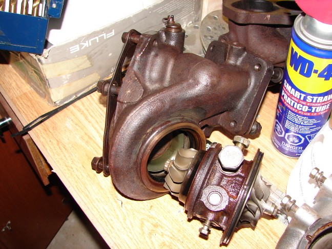 Hey it worked! I've split the turbo up to check it out. The above is a 9.6^2 exhaust turbine, and HR center section. 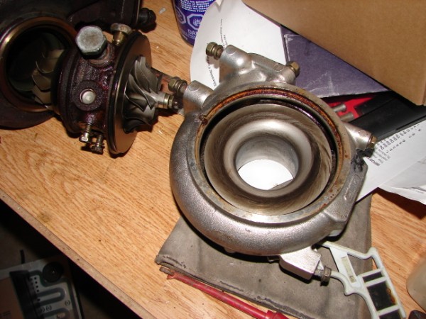 This is the comp housing side. It's a 16G6, not to be confused with either a big or small 16G. I still don't know if I want to spend the $200 to upgrade to a 20G wheel and TD06 compressor housing...I probably will though. On the exhaust turbine I ground off a tiny pin, and now both sections are 360deg clockable. i ordered up a 60mm external wastegate, so the original actuator is toast, and the internal wastegate will get welded shut. Chay ------------- 86 SE 3.4 |
Posted By: Romeo
Date Posted: 17 December 2009 at 1:58pm
|
That a perfect-sized snail. Small enough you don't have to wait a couple weeks for it to spool up (And therefore better torque), large enough to produce some good power figures. ------------- Never shift into reverse without a back-up plan. |
Posted By: CFoss
Date Posted: 17 December 2009 at 2:15pm
|
I hope you are right. From my calcs the compressor will be a bit small but I think the turbine should be right on the money. I didn't want to leave the spool too long, cause the intake system runs out of flow up top anyway. My idea was the car will be quicker if I maximize the low end potential rather than try to extend the high end torque. It will still extend the useable rpm range, but not to the extent that a big top end turbo would. Plus I like to get sucked back into the seat, but ease off at 120k...hopefully with the Honda in the rearview I'm starting to think I'm going to try the 16G6 compressor and log the intake air temps as I start boosting above 4 psi. If the intake air gets too hot too quick I'll know I need the bigger compressor for increased efficiency. If not, I saved $250. I'll just run it rich until I find out.
Chay ------------- 86 SE 3.4 |
Posted By: Capt Fiero
Date Posted: 22 December 2009 at 8:06am
|
Chay I am no expert when it comes to Turbo motors, however the 3.4 in your Fiero has more than enough punch off idle, if you can light up the tires now in first gear, then I would try to tweak that turbo to spool much later, like in the 2500rpm-3500rpm range. Once you clear 1st gear all your shifts will take place at a much higher rpm and the rpm drop will only go down to 3000rpms at the lowest. Congrats on getting it this far, I am sure no matter what happens you are going to have a blast with it. ------------- Capt Fiero 88 Fiero GT 5spd V6 Eight Fifty Seven GT V8 5spd. |
Posted By: CFoss
Date Posted: 22 December 2009 at 9:45am
|
You're right about the spool range. I expect it to spool right around 2500. Any lower could be a waste.
It may make boost threshold earlier, but I don't expect it to max boost until maybe 3000. This is all specuation, and has primarily to do with the turbine sizing, which is supposed to be similar to a .7ish a/r (Most run a .63T3, so I'm optimistic).
Ideally, I'd like full boost level by 3k, to take the useable rpm range from about 2.5k to about 6k. Max hp will still be around 5200-5500, but will be higher than stock of course. I did win the 24/28# injectors from a LT1 (There are either 24# or 28# depending on your fuel pressure setting). I should have plenty of fuel. And I got a 1227730 and harness, plus a 60mm wastegate cause I think I'll be bypassing quite a bit at initial low boost settings and I don't wan't creep, now to get a bov and figure out the $58 programming (Syclone/Typhoon)....should take me at least another 2 days eh?
Chay ------------- 86 SE 3.4 |
Posted By: CFoss
Date Posted: 22 December 2009 at 9:57am
|
As a note to your original question, as long as you have good traction, the later you leave the boost the slower the car will be in the quarter. If you boost later you may have a higher final speed, but it will be slower overall. Given that I'll be on the street/autocross, I'm looking for more low end. The Fiero manifold flows ok at between 2.5k and 5.5k, then it dies...this is common knowledge. So, if you bring the boost on late, it will feel like you are extending the torque way up into the high rpms, but you will miss the oportunity to build higer torque earlier.
From Displacement = VT+1/2AT^2, the faster you get going earlier, the further you go. Or, the other way to look at it is getting going faster earlier raises your average speed more than having a high top end speed for a shorter period of time (And therefore reduces your time for a given distance). This is critical on a short duration course like a 1/8 or 1/4 mile (Or god forbid the street). It's pretty wordy, hope that makes sense. I just have to get the power down once I start making it, but that's the fun part. The car already goes fast enough for me. It doensn't get going nearly fast enough though. (From that video...Rotary? I want STUMP PULLING torque). So, I've thought about it a bit.
Chay ------------- 86 SE 3.4 |
Posted By: Capt Fiero
Date Posted: 02 January 2010 at 11:18pm
|
Any updates? ------------- Capt Fiero 88 Fiero GT 5spd V6 Eight Fifty Seven GT V8 5spd. |
Posted By: CFoss
Date Posted: 14 January 2010 at 4:11pm
|
Yeah. I bought a 60mm wastegate and LT1 24/28# injectors. The wastegate was a ebay special, but when I recieved it I was pleasantly surprised at the quality. I opened it up to find a very good thick silicone diaphram and solid spring action. The only problem was it was supposed to actuate in the range of 4-8psi, but I found it cracked at 10psi and was full open at 15psi. So, I cut the spring and now without preload it cracks at 3psi and is full open at 7psi, and can be adjusted to crack up to 10psi if wanted. So I'm happy with that result. The LT1 injectors are shorter than the fiero injectors. Also, the top to keeper groove was onger than on the fiero. So, I made a new groove in the injectors which is closer to the top, then the length under the keeper is right on. It still has lots of length to seal up top in the fuel rail...Needless to say I'll be pressure testing thoroughly. Also, I found this on Pennocks by accident: 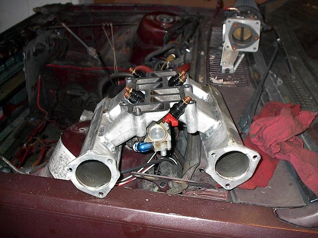 I have a spare middle intake so I think I'll try to make one. I may end up needing a bigger turbo after though!!!!! It's supposed to make a big difference in the rpm range, especially for a 3.4. Chay ------------- 86 SE 3.4 |
Posted By: CFoss
Date Posted: 14 January 2010 at 10:34pm
Had some fun tonight...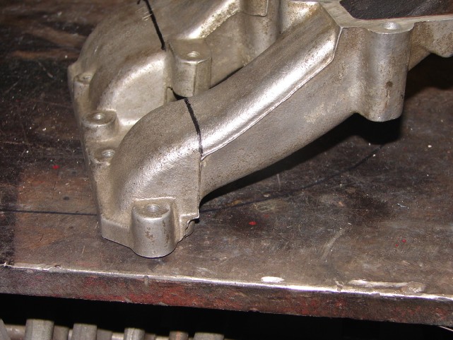 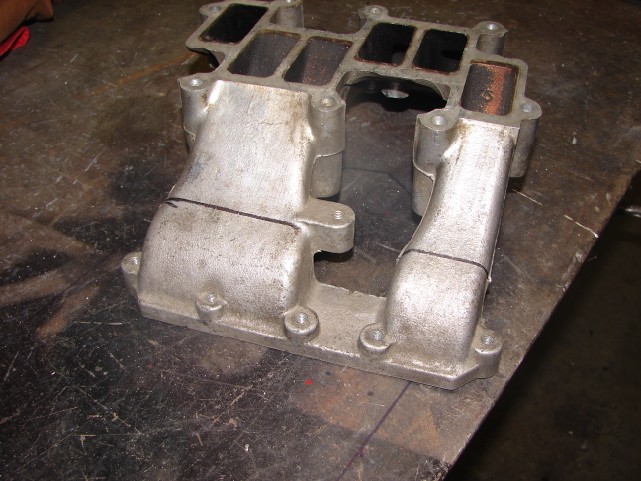 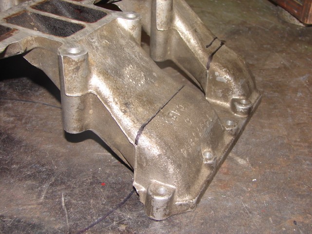 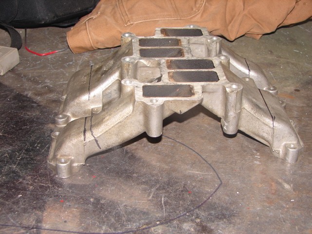 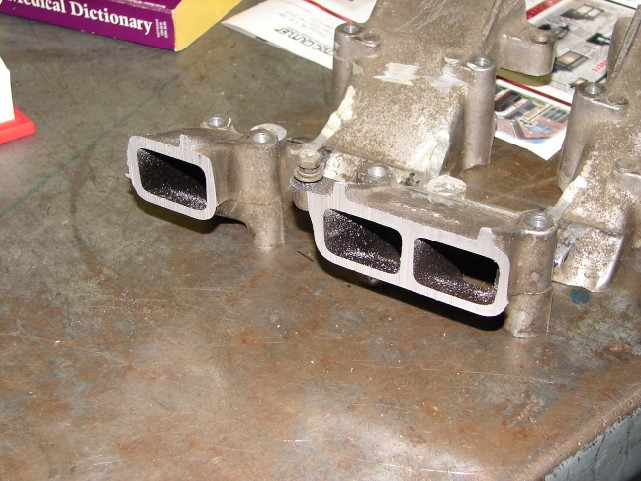 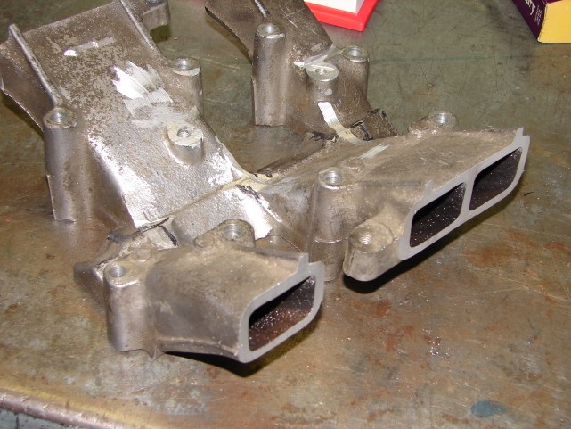 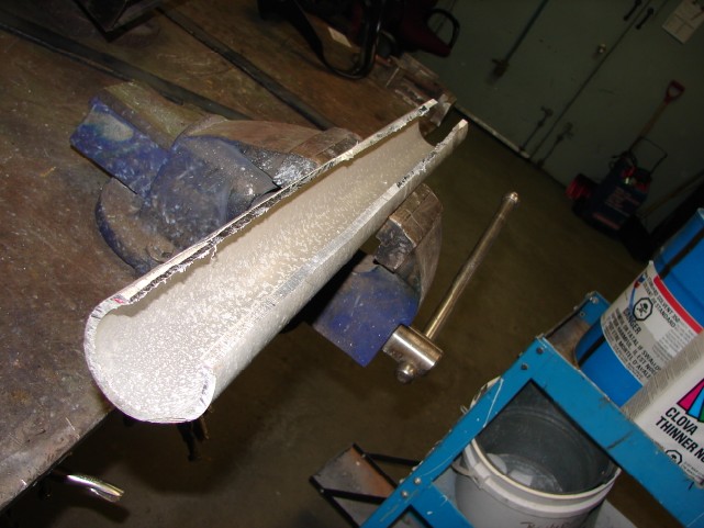 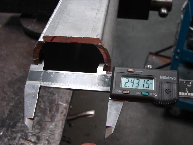  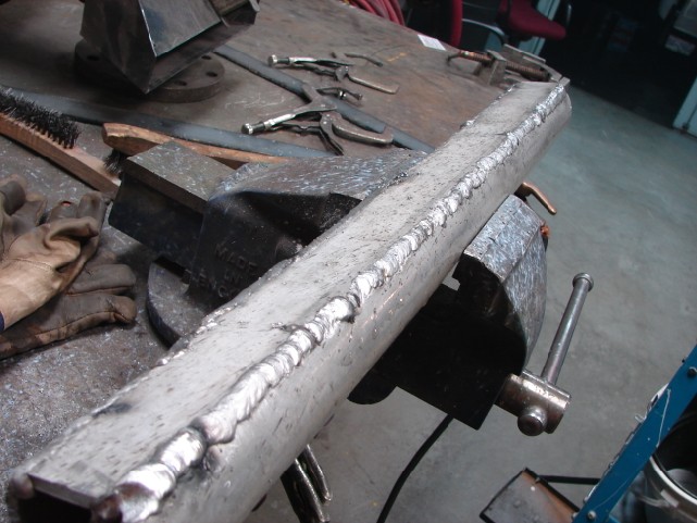 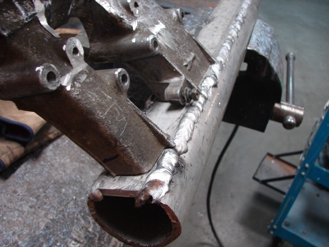 I need to add a full tubular section to accomodate the throttle bodies, but not bad overall. Pretty simple job so far. Chay ------------- 86 SE 3.4 |
Posted By: Patrick
Date Posted: 15 January 2010 at 11:24pm
|
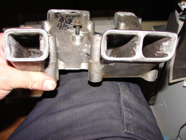
Hey Chay, looks like you're having some fun there! I'm just curious, what was your reason for cutting the runners as oppossed to mounting the tubes on the ends of the original runners? I'm not suggesting you should or shouldn't have, I'm just wondering why you chose the path you did? Here's a couple of images of a dual-plenum manifold I almost bought from the Mall at Pennock's over a year ago. I eventually decided against it for three reasons... 1) More trouble than I needed. 2) Made of steel and heavy. 3) Ugly as sin.
|
Posted By: CFoss
Date Posted: 16 January 2010 at 2:17pm
|
There is a thread in pennocks that I got this from...there are a bunch of guys with cut down runners. They say they are getting better low and top end performance. I don't know too much about design on intakes, but I suspect the low end performance comes in the decreased resonance point because of the shortened runners, and the top end because of removing the obstruction in the upper intake allows more total airflow. Also, there is a height issue if it gets too tall. And cutting the middle eliminates one 90deg ish turn the air has to make in the middle plenum. That was the long answer. The short one is someone did it before and had success, so i don't want to reinvent the wheel. As for the above...totally agree! Chay ------------- 86 SE 3.4 |
Posted By: Dr.Fiero
Date Posted: 16 January 2010 at 3:17pm
The guy who makes the Trueleo intake used to make both a short and long runner version. He discontinued the long runner version, saying that the short length one outsold the long, and had pretty much the same performance overall, with way more in the bottom where most people run anyhow. So.... Short is good. |
Posted By: Patrick
Date Posted: 16 January 2010 at 6:59pm
|
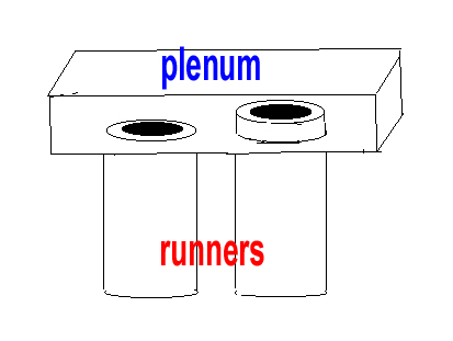
Chay, I don't remember the name given to this technique/addition, but had you looked into adding "extensions" to the runner tubes where they enter the plenum? They stick up a bit from the floor of the plenum. It's supposed to help flow. Do you know what I'm talking about? Okay, don't laugh... I tried to draw it for you. The runner with the extension thingy is on the right. The shape isn't right, but it should be good enough to get the idea across.
Keep in mind I was only wondering why Chay cut the last inch or so off the runners.
|


Posted By: CFoss
Date Posted: 17 January 2010 at 10:52am
|
They are called velocity stacks, I saw them in another professionally done intake. I hadn't considered it, but it actually might be easy to do...just clean up the runners for the thickness of my pipes plus a bit more, and enlarge the holes in the pipes to accept a bit of the runners into them. Then I don't have to be so carefull to match the ports too, and weld the outside of the connection. I'd like to research it some more...it's curious how it would increase flow. Like I said I have seen it so I'm a believer....just want to know how it works. Chay ------------- 86 SE 3.4 |
Posted By: CFoss
Date Posted: 17 January 2010 at 10:53am
|
I made note of the discontinued Truleo...when all arrow point in the same direction it makes decisions like that easier. C ------------- 86 SE 3.4 |
Posted By: Patrick
Date Posted: 17 January 2010 at 11:00am
|
Hey, now you're talking. Sounds great! Keep in mind they need to be trumpet shaped.
Yes, "velocity stacks". That's the term I couldn't remember.
|


Posted By: CFoss
Date Posted: 17 January 2010 at 11:01am
|
Looks like all the pro velocity stacks have a bevel on the inside...so I'll bevel the runners before I weld them into the plenum and it should accomplish the same thing. Good tip. Chay ------------- 86 SE 3.4 |
Posted By: CFoss
Date Posted: 17 January 2010 at 3:16pm
|
I think the ones in the middle of your pic are what I'll try to d. Not too proud, but enough to try the bevel. Now, is that curve eliptical or logaritmic? Ha ha. I wish I could get an eliptical dremmel. Chay ------------- 86 SE 3.4 |
Posted By: CFoss
Date Posted: 17 January 2010 at 8:55pm
|
Ok, for injectors...here we go... There are two measurements which are important. The grove to top height and the grove to bottom height. Then, there is the flow, in CC or in pounds/hour. 500cc is about 49 lb/hr, so you can convert. Also, there is the injector impedance to consider. First, the group of injectors I'm messing with: 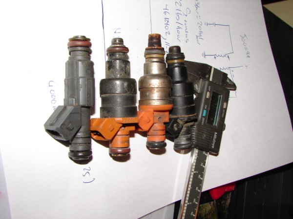 How did these get upside down??? Ha ha. The left is a LT1 injector(24lb/hr)...I cut the top groove, the bottom is stock for reasons you will see below. The second is a 1996 3.8L dodge injector(22 or 24#/hr), a Siemens Deka 666A. the third is a 1996 3.0l dodge injector, a nippondenso INP-066 (19 OR 20#/HR) and the last is the Fiero stocker (14#/hr). More on the stockers... 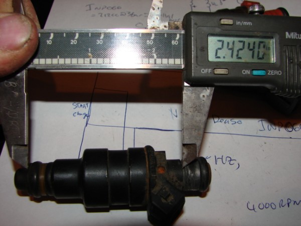 2.42 is the body length, and is critical because this is the distance between the fuel rail and the lower manifold. If this isn't right there is a good chance you will have vaccuum leaks and it won't seat in the lower manifold far enough for a good injection into the air path. 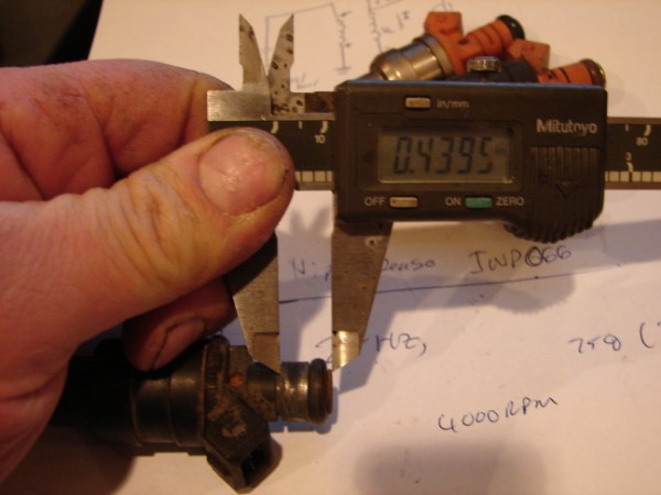 This is the ring groove to top measure on the stocker. this will fully insert the top on the injector into the rail. The port is cylindrical to the end where there is a small bevel to ease insertion into the rail. as long as the o-ring is past the bevel, there is no difference in sealing from there on up. This allows a smaller groove to top dimension to be used, which allows many injectors to interchange. Nipondenso (19-20#/hr): 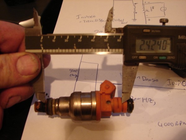 The body height is the same so this is a good candidate. How is the groove to top height? 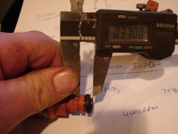 At .37, it's smaller than stock (.43), but should still easily seal. This is my fall back set of injectors. They are high Z so no problem with the ecm. Siemens Deka (24#/hr): 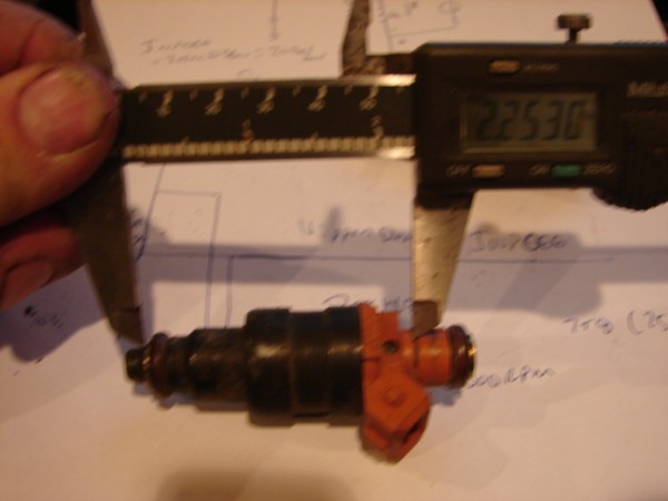 2.25", uh-oh. It's a no go. Too bad, the #/hr is what I'm after. Ok, LT1 injectos (GM 2561462, Bosch 280 155 931) at 24#/hr. These are rated at 28#/hr, but at higher pressure, so they are at about 24#/hr where I want to run (44psi or so). 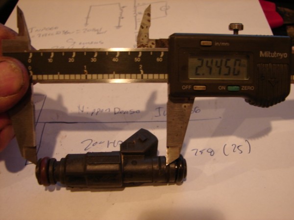 You can see the original groove (Lower) and the groove I made. From the groove I made the body length is perfect (.02" difference, no big deal). So how is the g-top measure... 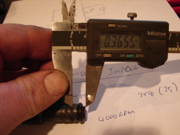 .36, not bad, not super good. It will seal though. It's a very similar measure to the nippondenso. Here is a few shots of the rail and lower manifold: 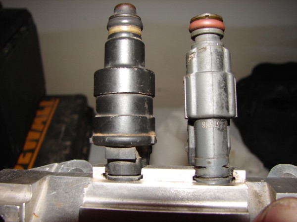 Stock vs LT1 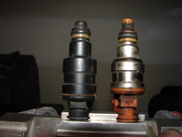 Stock vs nippondenso 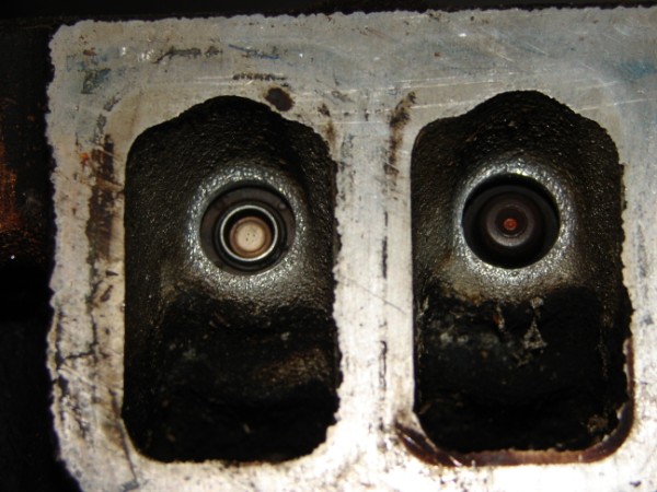 LT1 vs stock 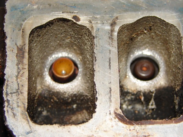 Nippondenso vs stock 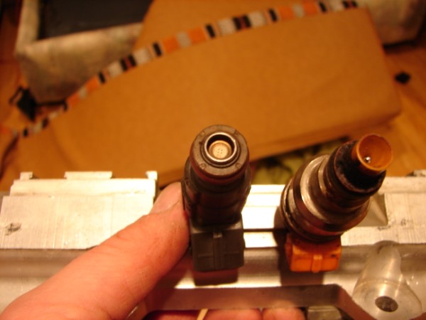 LT1 (disk pattern) vs nippindenso pintle Chay ------------- 86 SE 3.4 |
Posted By: Patrick
Date Posted: 18 January 2010 at 11:35am
|
Thanks Chay, I hope it yields you a few extra ponies. Someday you'll have to make it across the pond to a club function so we can all meet you and your Fiero.
|
Posted By: CFoss
Date Posted: 18 January 2010 at 8:27pm
|
One day. When I was over there I never made it though. Too much family commitments. I did up the runners, as best I could. The pics don't really do it justice, but: 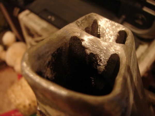 Sort of trumpetty....I made sure the corners were very rounded and smooth. 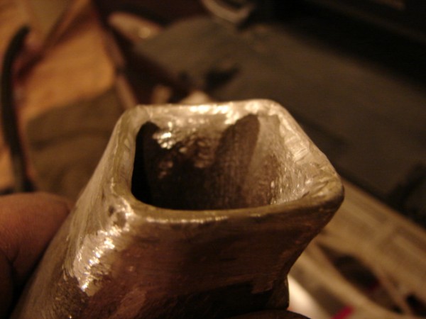 Will it work? Who knows. Chay ------------- 86 SE 3.4 |
Posted By: Patrick
Date Posted: 18 January 2010 at 8:38pm
|
If it doesn't work, you've only lost a bit of time. If it does work, I want at least half the credit.
|
Posted By: Capt Fiero
Date Posted: 18 January 2010 at 10:16pm
|
Flow-bench numbers for Stock intake and SR14 & LR17 below.
------------- Capt Fiero 88 Fiero GT 5spd V6 Eight Fifty Seven GT V8 5spd. |
Posted By: CFoss
Date Posted: 19 January 2010 at 10:57am
|
Yeah, the numbers are hard for me to put into real world practical terms. What I'd like to know is at 5500 rpm, what is the difference in flow? I have a 3.4, with a higher lift cam. It stands to reason that this combo will benefit more from a free flowing intake than a stock 2.8. I definately run out of air before 5k. It's quite annoying. Anyway look at these stacks: 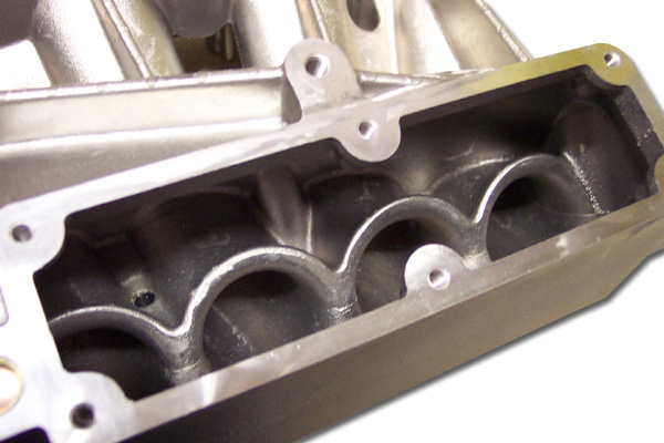 They look a lot bigger than what I'm making. I think what I might do is redo the plenum. This time I'll cut the holes to accept the runners in the flat plate, then insert the runners and weld tabs on the runners to create a horn style velocity stack (Think like a tweeter horn in reverse). Then weld the runners to the flat plate, and finally the flat plate to the tubular material. It would be more effective that way i think. Chay ------------- 86 SE 3.4 |
Posted By: CFoss
Date Posted: 19 January 2010 at 7:14pm
|
After doing a bit more research I found lots of V stack pics. They have bigger and more circular radiuses, but mine will work somewhat. It's better than not doing the shaping for sure. With our oval and disimilar shaped runners it will be hard to get anything comercial to fit, so shaping the oem seems to me the best solution to keep it simple. May of the V stacks don't extend that far into the plenum, so I'm going to try 1/4-1/2 inch. Chay ------------- 86 SE 3.4 |
Posted By: Patrick
Date Posted: 19 January 2010 at 10:24pm
|
I think that's a great idea. Will you be fabricating a balance tube between the two plenums?
|
 I was disappointed when you posted the image below because I felt you had severely limited yourself with what you could do with the plenum. Doing it over again in the manner mentioned above will give you ample opportunity to do a much better job.
Posted By: CFoss
Date Posted: 21 January 2010 at 9:29am
|
The shape of the plenum will be the same, it's just that it will be assembled in a way where I can work the interior. It's a space issue on the top of the engine. Too big a diameter and the trunk lid will hit. I think the size is adequate: 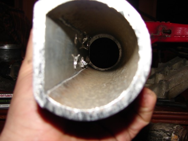 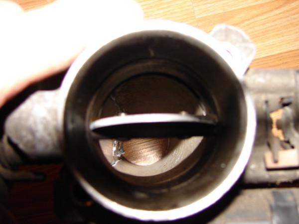 As you can see the throttle body fits ok (It's big enough). The junk in the interior is from drilling the corners of the runner entrances. This time I will start with doing the flat piece. I will cut out the runner entrances and then insert the runners, tack it in place and then build the horns on the 'inside', the to finish it, weld on the tube section. This will help 2 fold: 1) The runners enter at an angle, so I can weld to fill the gap left by the angle on the inside 2) I can build better V stacks because I can make them bigger and shape them better, and have access to machine them This is what I have in mind as a model (It's a bit fuzzy).  It'll end up somewhat different (More horn type than trumpet type), but that's the idea. Chay ------------- 86 SE 3.4 |
Posted By: CFoss
Date Posted: 21 January 2010 at 9:31am
|
Yeah, I'm going to do a 1" balance tube, but I want to mock it up on the engine before deciding where it's going. There are some other provisions as well, like egr (I think I'll delete it) and map sensor, brake vaccuum source etc. Chay ------------- 86 SE 3.4 |
Posted By: CFoss
Date Posted: 21 January 2010 at 9:35am
|
Found what I'm looking for: http://cgi.ebay.com/ebaymotors/ws/eBayISAPI.dll?ViewItem&item=200384376524&ru=http%3A%2F%2Fmotors.shop.ebay.com%3A80%2F__%3F_from%3DR40%26_trksid%3Dm39%26_nkw%3D200384376524%26_fvi%3D1&_rdc=1 - HERE http://cgi.ebay.com/ebaymotors/ws/eBayISAPI.dll?ViewItem&%20;item=200384376524&viewitem=%20 - |
Posted By: Patrick
Date Posted: 21 January 2010 at 10:05am
|
Oh, I knew what you meant, and I agree that's by far the best/only way to do it.
Holy sheeeeit.... $39(US) each! Do you really think it's worth about $288 (six velocity stacks, shipping, dollar conversion) to buy those particular pre-made velocity stacks rather than to fabricate something yourself (or to find a less expensive alternative)?
|


Posted By: CFoss
Date Posted: 21 January 2010 at 5:22pm
 They 'neck down' before they turn. I'm back to my original idea, but I will redo the plenums to take advantage of the access to weld it up nice. Chay ------------- 86 SE 3.4 |
Posted By: CFoss
Date Posted: 21 January 2010 at 5:30pm
|
This was lost from my last post (Before the pic): I bought some 3/4 inch aluminum plate and tried to make some stacks. It is really difficult to match the angles and sweeps on the middle intake, so I'm slacking off with that idea. When I look at the intake it sort of does the vstack thing where I cut it anyway: Hell no...I wouldn't buy the ones off Ebay..they wouldn't fit anyway...it was just the idea I liked. It's going to be way hard to do though. This is where I got to: 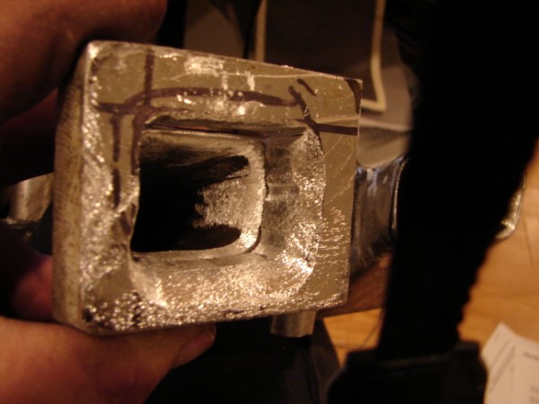 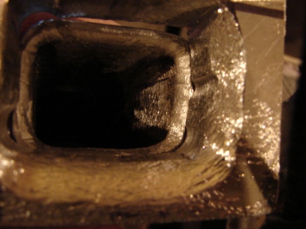 I think it will be ok without these. I have some thinner plate, maybe I'll try that. C ------------- 86 SE 3.4 |
Posted By: CFoss
Date Posted: 21 January 2010 at 5:46pm
Ok, new idea: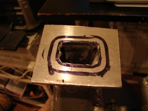 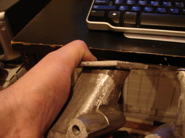 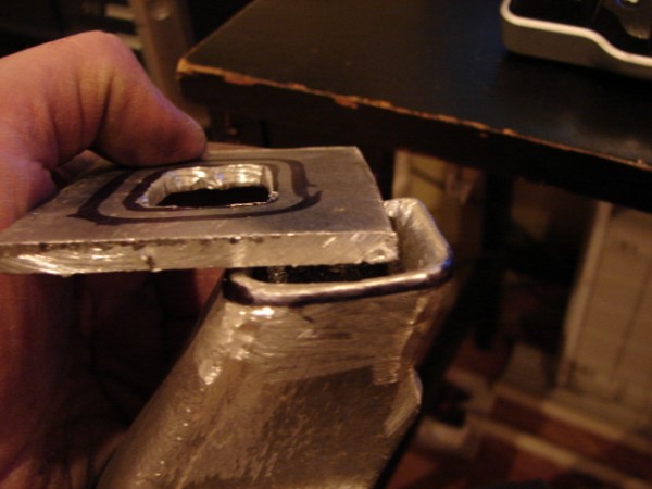 The plate is .2" thick. A far cry for .75" eh? I cut the hole smaller than the runner, so I'll poke the runner through the plenum wall, wled the plate on and machine it to match the runner, then weld the plate up to the interior of the plenum and smooth it out and it should work good. The stack will be about .5" deep then. Not huge, but enough to have an effect. Chay ------------- 86 SE 3.4 |
Posted By: CFoss
Date Posted: 22 January 2010 at 7:42pm
|
I found out when I put the new middle manifold on the lower one that the reason the runners come up is the valve covers get in the way. When I look at the pic I posted in page 2 there are two flat sides...one where the runners hook up and one where they need to clear the valve covers. So, I need to redo the plenums for sure! I'll post the build on them when I get there. Chay ------------- 86 SE 3.4 |
Posted By: Patrick
Date Posted: 22 January 2010 at 9:49pm
|
Oops! Just run her without valve covers.
|
Posted By: Capt Fiero
Date Posted: 23 January 2010 at 3:02am
|
For the record, Edlebrock makes a custom sheet metal valve cover for the 2.8 that fits nice on the Fiero. Due to its rather thin nature, it is also much smaller than the Fiero valve cover. That might be an easy solution for you, price was IIRC fairly reasonable about under 50 bucks and they are a nice polished chrome. Fire451 has them on his 2.9 V6. Mopac even has these in stock on the shelf locally. ------------- Capt Fiero 88 Fiero GT 5spd V6 Eight Fifty Seven GT V8 5spd. |
Posted By: CFoss
Date Posted: 24 January 2010 at 6:23pm
More pics on the build and what i was trying to explain above: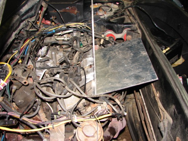 As you can see, without the upturned portion of the runner you have to angle the bottom of the plenum like above. 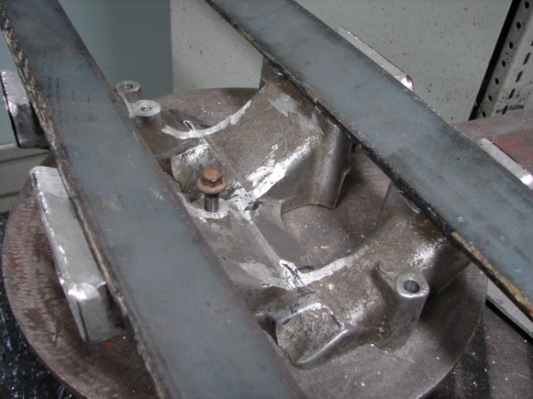 To keep everything straight, I used these pieces of steel lined up on the bolt holes, and a square to mark them so I could come across 90 deg from the long axis. 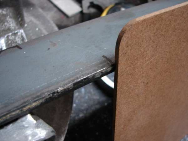 I used a square piece of wood (clipboard) on the end mark, then slide the bottom piece until it contacts the clipboard and clamp it. 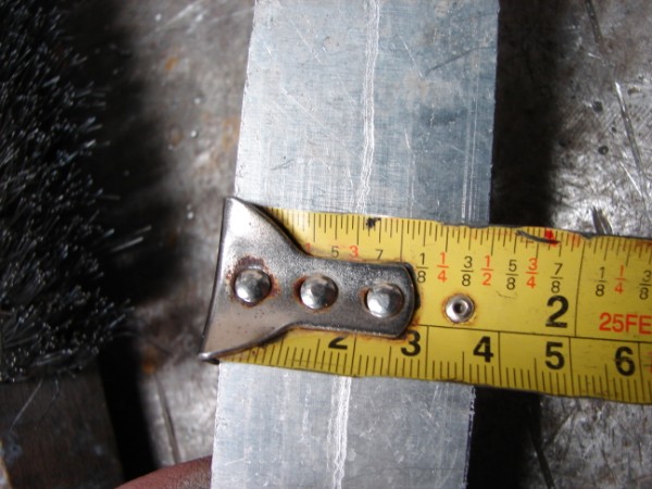 37mm bottom peice width (13" long) 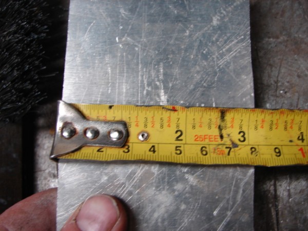 78mm vertical peiece, then connect them with a round piece: 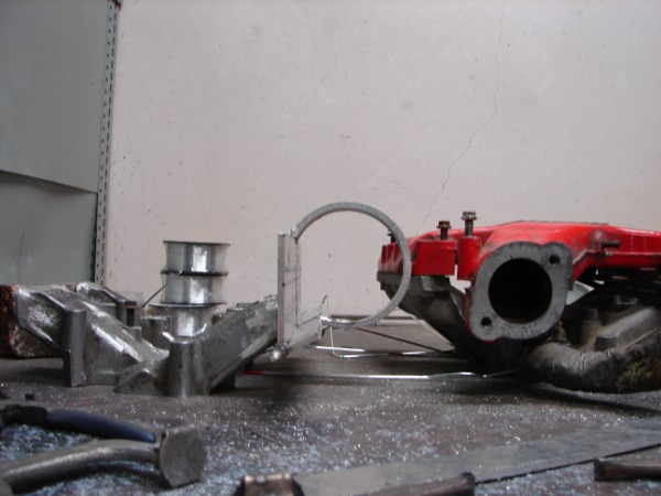 The height is a little taller than the original (7" vs 6.5", but i checked last night and it fits. So, now that I have a good profile, I'll do the complete unit. 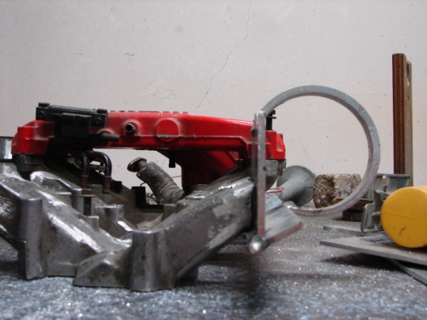 It's wider too, but there is lots of room to fit it in. Chay ------------- 86 SE 3.4 |
Posted By: Patrick
Date Posted: 24 January 2010 at 6:38pm
|
How long are you going to make each plenum (is it 13"?), and where (relative to the original TB location) will the two throttle bodies end up? |
Posted By: CFoss
Date Posted: 24 January 2010 at 10:28pm
|
The plenums will be 13" long. This is not from any calculation. I've read that for fuel injected engines, plenums from .5 to 1.5 times engine volume will work. Larger = more hp, smaller = better response. Because I will be adding boost, larger did not seem necessary. As for the second question, I'm not sure. The picture with the metal above has 13" pieces. They will end up just off the end of the valve covers by and inch or two from memory. I think they will be shorter and stubbier than the original. Kind of on either side of the dist. is where the tbs will end up I think. Chay ------------- 86 SE 3.4 |
Posted By: CFoss
Date Posted: 25 January 2010 at 5:44pm
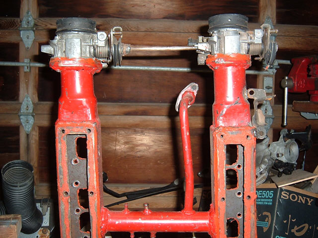
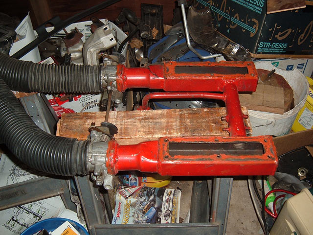
Some more pics of the final mock up...it's huge!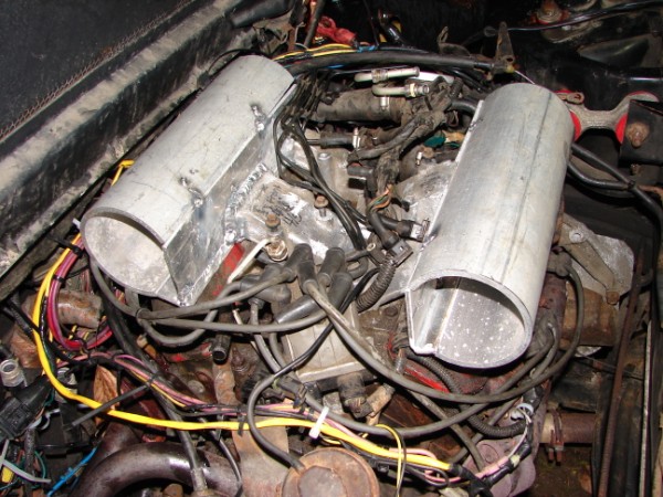 Man, I can't wait to fire this thing up! Build pics: 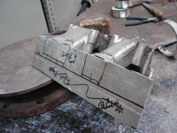 I tack welded the first side plate on, then open it up: 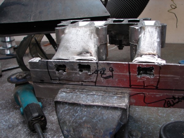 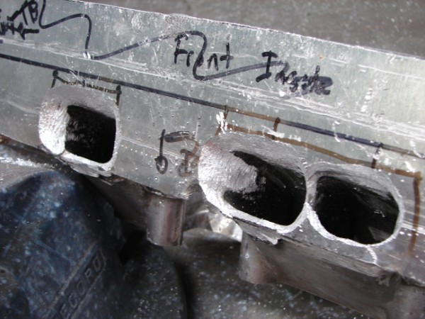 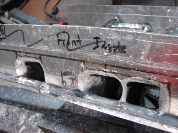 The lead ins are fairly deep, but don't protrude into the plenum because there is no room on the bottoms due to the valve covers. the other areas are pretty good though. I still have to polish them up. 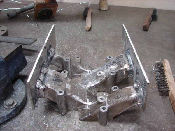 Tied on the other side, opened it up as well. This is a pretty long process with a drill and file bit. 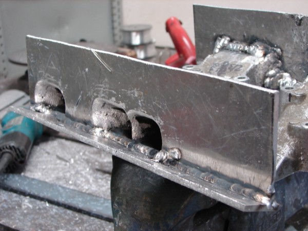 I tied on the bottoms at an angle to clear the valve covers, then welded inside and out (Not yet cleaned up). 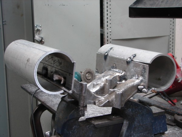 I finished today by tacking on the big tubes so I could check it on the car. It fits!! There are a couple of complications though: 1) The ignition coil and lifting ring on the back of the engine need to be relocated 2) The breather tube coming from the top of the front valve cover won't fit under the plenum. I'll block off the original and put the breather into the end of the valve cover. Chay ------------- 86 SE 3.4 |
Posted By: Patrick
Date Posted: 25 January 2010 at 6:21pm
|
Looking more and more like the starship Enterprise.
|

Posted By: CFoss
Date Posted: 25 January 2010 at 8:12pm
|
Nice nacells. That might work as a pick up line at a trek convention (If there were any girls there). Man, that's cheese. The cheque is in the mail btw. No, really. Chay ------------- 86 SE 3.4 |
Posted By: Romeo
Date Posted: 25 January 2010 at 11:20pm
|
LOL Oh this devolved so rapidly... ------------- Never shift into reverse without a back-up plan. |
Posted By: Patrick
Date Posted: 28 January 2010 at 2:35pm
|
Got it today, thanks. Let me know when the package arrives. Should be there by now.
|
Posted By: wayneh70
Date Posted: 28 January 2010 at 3:57pm
It's not cheese it was in the movie!!!! Scotty: "The Enterprise? I�d like to get my hands on her ample nacelles, if you�ll pardon the engineering parlance." Now back to your regularly scheduled topic  |
Posted By: Patrick
Date Posted: 28 January 2010 at 6:50pm
|
Wayne, the first step to recovery is to admit you have a problem.
|


Posted By: Capt Fiero
Date Posted: 28 January 2010 at 9:18pm
|
LOL Patrick, there are probably a lot more Star Trek fans on this forum that you know. I personally know about 1/2 dozen forum members that went and saw it on opening night, I know becuase they were there with me. ------------- Capt Fiero 88 Fiero GT 5spd V6 Eight Fifty Seven GT V8 5spd. |
Posted By: Patrick
Date Posted: 28 January 2010 at 11:27pm
|
Don't get me wrong Dave, I really like all the various incarnations of Star Trek. I still fondly remember watching the original series on TV back in the mid 60's. However, I'm not such a devoted Trekkie that I can recite obscure lines from a movie.
|
Posted By: CFoss
Date Posted: 01 February 2010 at 11:52am
|
I got the throttle body and the bits...many thanks. Chay ------------- 86 SE 3.4 |
Posted By: Patrick
Date Posted: 07 March 2010 at 11:23pm
|
No updates?
|
Posted By: CFoss
Date Posted: 08 March 2010 at 12:00pm
|
Not yet, I've been distracted with other things. The next steps are to mount the throttle bodies, throttle cable bracket, map, and balance tube and clean it up a bit. It's a bunch of fiddling work, but I'm taking photos so it'll be well documented. Chay ------------- 86 SE 3.4 |
Posted By: CFoss
Date Posted: 08 March 2010 at 12:01pm
|
I've been thinking of getting a "NACELL" personalized plate though. Chay ------------- 86 SE 3.4 |
Posted By: CFoss
Date Posted: 17 March 2010 at 2:00pm
Ok, a bit of an update.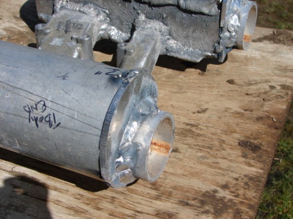 I added these um, nipples, to the end of the plenums. I would have rather not, but I needed the extra length to clear the distributor and also I want to do a direct link (Welded rod) between the throttle bodies rather than cables which are always streching and binding and all that stuff. Plus, I don't want to make it a Toyota (Sticking at WOT). I didn't weld the plates to the plenums until I fit it on the car, looks like it will work well. A couple of build pics: 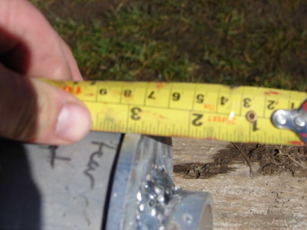 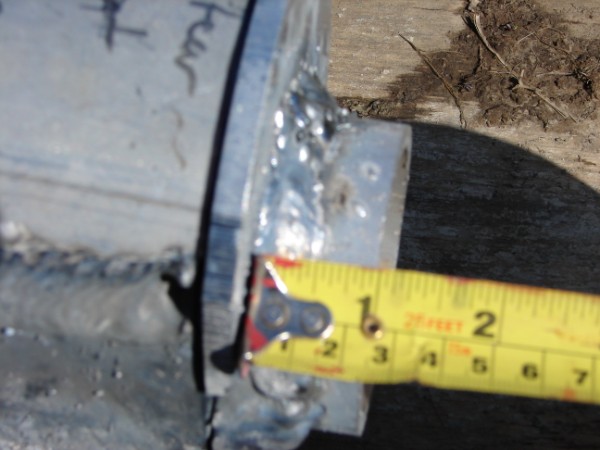 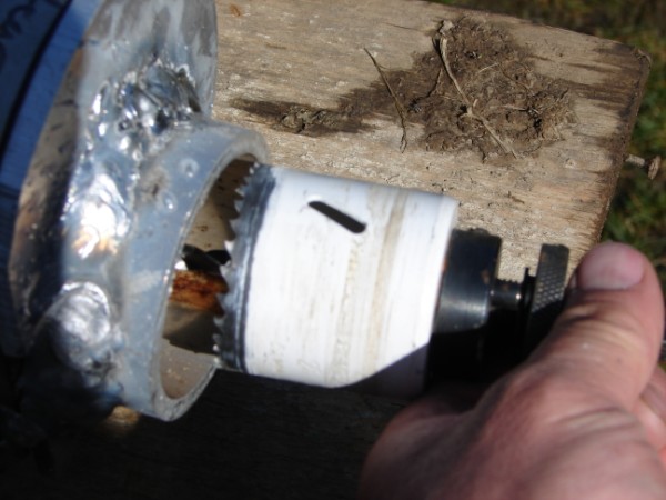 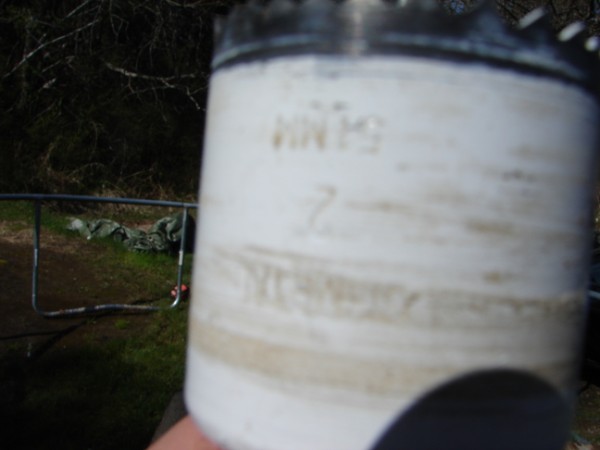 2", not sure if you can see that. 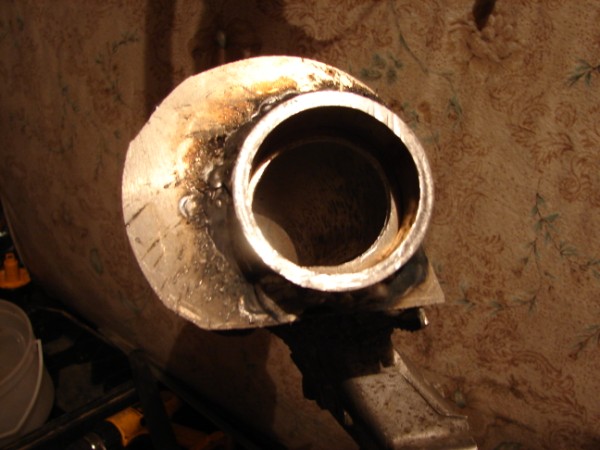 After the hole saw. 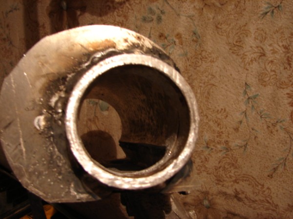 After the cleanup with this: 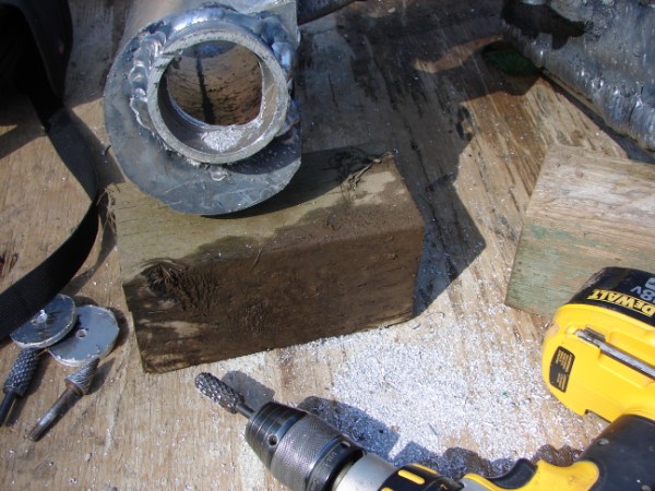 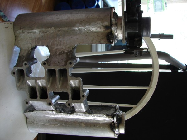 The next step...mount the bodies... 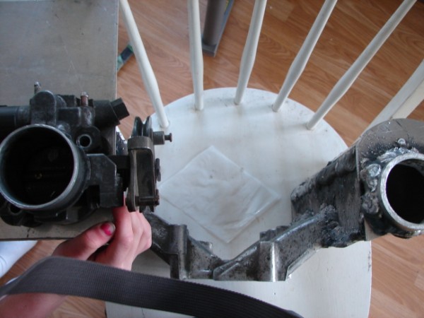 Chay ------------- 86 SE 3.4 |
Posted By: CFoss
Date Posted: 17 March 2010 at 2:04pm
|
Oh, yeah, the offset is so the throttle pulleys will clear the plenum and it works well. If i had to do it over again, the plenums would be a smaller diameter and longer, and the runners would be a bit longer to clear the valve covers. It was cutting the runners too short which forced my hand on this. The change might sacrifice a bit of performance, but would be way easier to build. Chay ------------- 86 SE 3.4 |
Posted By: Patrick
Date Posted: 17 March 2010 at 3:55pm
|
Looking good. Did you end up with anything resembling velocity stacks inside the plenums?
|
Posted By: CFoss
Date Posted: 17 March 2010 at 5:41pm
|
There is no room for them to protrude externally into the plenums because of the angle of the runners and their proximity to the bottom of the plenum (Which is limited due to the valve covers). Plus, with the spacing of the runners which have 2 runners together, then one apart, what would you do with the wall common to the 2 cylinders? I guess you're looking at a full custom like the truleo to split the runners apart and maintain their equal length. If the runners were longer and the plenum was smaller you might manage something in the way of an external v stacks. I did shape the entrances to the runners in a horn shape though. They look pretty flowy to me. Chay ------------- 86 SE 3.4 |
Posted By: Patrick
Date Posted: 17 March 2010 at 8:19pm
|
Is that mechanical engineering lingo?
|
Posted By: ARTIC-1
Date Posted: 17 March 2010 at 9:53pm
|
HI Guys,bin following Chay progress in this project,nice job on the metal
work.when i seen the pics of the end plates welded on the intake,i thought nice job on the Alum weld.but the pics you just posted,the welding don't look the same as the other?,what happend!myself i have bin a fabricators for over 30 years,aluminum is my field of expertise.Chay your an excellent fabricators,so please don't take this post the wrong way,just trying to help out a bit here if i can,great job love to see it all come to together an working well for you Cheers ------------- SNOW MAN 87-GT/AUTO-2.8_ WHITE 88-TTop/ Duke-2.5. RED |
Posted By: CFoss
Date Posted: 17 March 2010 at 10:16pm
|
Well, I've been an aluminum welder for .5 years. Ha. I don't always do it right...brush, solvent, preheat etc. Sometimes I have to git er dun within the wife's timetable, so the welds aren't fantastic. I grind them off and check em with with stain penetrant (My old man was a NDT tech...very handy) so I can be sure they will hold vacuum/pressure. Today I ground and rewelded some of the stuff above so it looks better now. I had the welder running about 180A with .035 wire so it was hotter than it really needed to be, but the penetration was excellent and when I grind it down it should look great. Flowy? Well, it's better than using effort as a verb, but not much. (I'm efforting to get it done...) Chay ------------- 86 SE 3.4 |
Posted By: ARTIC-1
Date Posted: 17 March 2010 at 10:54pm
|
Hay chay,great job,sounds like your in the ball park with the welding heat
an wire,the biggest prob with ALUM is contamination in the aluminum,when you use a stone base grinder wheel it will contaminate your base metal.an you will get porosity in the weld.a 316 S/S brad wire wheel will remove most the contamination from your base befor you weld.Don't use a stone base cutting wheel (ZIPCUT) to fit your job up.tac it up then gouge it with a skillsaw if needed an then brush it with S/S wheel or hand brush.not a steel brush,the carbon in the steel brush will stick to your Alum base metal giveing you that porosity weld.an again grate job,can't wate to see it all come togather. CHEERS my ALUM snowboards http://www.youtube.com/user/Artic1snow - ------------- SNOW MAN 87-GT/AUTO-2.8_ WHITE 88-TTop/ Duke-2.5. RED |
Posted By: CFoss
Date Posted: 18 March 2010 at 4:49pm
|
100% correct. Sometimes I'm just lazy. Sorry to say it. It looks really bad in print. True though. I'm going to clean everything up and then check it out a bit. Chay ------------- 86 SE 3.4 |
Posted By: CFoss
Date Posted: 18 March 2010 at 8:52pm
Some more pics with the welds cleaned up on one side...first, the ugly (The undone side):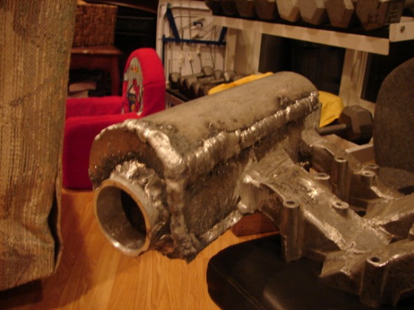 Now two shots of the excess ground off on the other side: 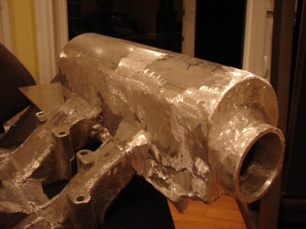 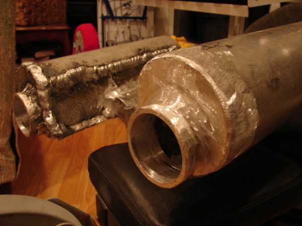 I think it looks ok. Hopefully they test out well. Chay ------------- 86 SE 3.4 |
Posted By: ARTIC-1
Date Posted: 20 March 2010 at 10:01pm
|
Looks good buddy,testing soon?Hay have you ever tried a little Wax on your
tooling.grab an old candle,or bar of soap! an dress your burrs an grinders with it,works vary well with the tooling.can't wate to see this all come together,grate job. ------------- SNOW MAN 87-GT/AUTO-2.8_ WHITE 88-TTop/ Duke-2.5. RED |
Posted By: CFoss
Date Posted: 21 March 2010 at 6:05pm
|
I've heard of it but haven't tried it. I'll try it on the next set of welds. Next up, crossover tube and throttle cable bracket and then map, iat and brake booster taps. Chay ------------- 86 SE 3.4 |
Posted By: CFoss
Date Posted: 24 March 2010 at 8:42pm
|
Ok, a bit more work done. I made some plates for the tbs to mount to: 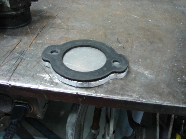 I've been trying to figure out how to connect the TBs together so that they will work well. I didn't want to use cables because they stretch etc, so a connecting bar was my choice. This means I only have to use 1 throttle return spring so I'll avoid having two and a very stiff throttle pedal. So, to remove the other spring is pretty easy actually: Step 1: 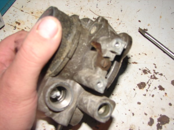 This TB already has been stripped of the tps, iac, etc, so to finish it up I'm removing the tps actuator by removing this screw. You can pull the shaft out to the pulley side now Step2: 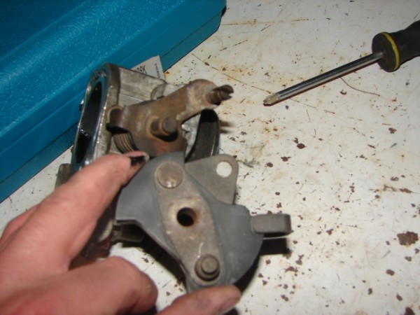 On the other side pop off the retaining clip and slide the pulley off. Step 3: 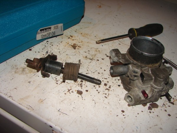 Pull off the spring and reassemble I also made up some plates for the throttle bodies to mount to:  I holed out the middle to match the gasket. Now, to allign and attach the throttle bodies so that the shafts are straight...time for some thinking. I was lucky enough that the pipe I've been using has a very close inside diameter to the outside diameter of the TB. Fits like a glove actually: 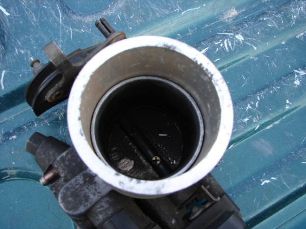 That gave me an idea. If I could get the right width, then use the pipes to match the height, then all I would have to do is allign the shafts and weld it together... 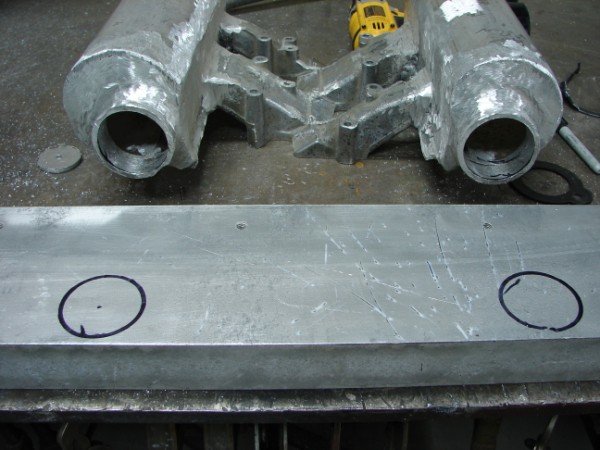 This piece of aluminum is my straight edge. I traced the circles from the intake to get the widths right. 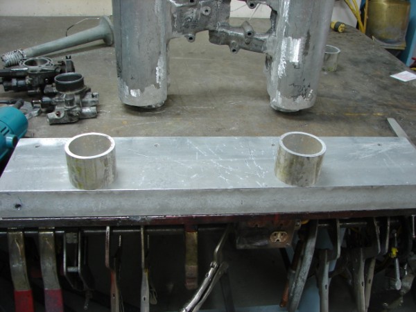 Then I tack welded the pipe over the traced circles 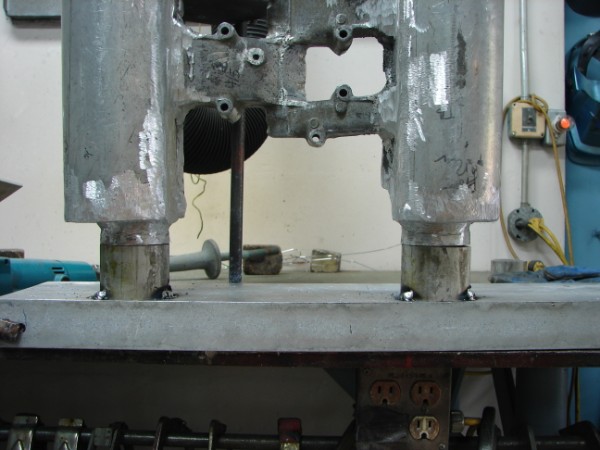 A quick check for accuracy...looks good to me 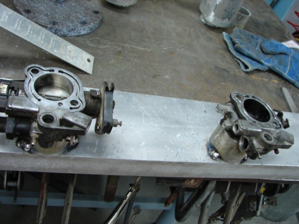 And here the tbs are in their temporary homes...now to connect them 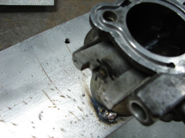 This little piece seems pretty small to weld to, soooo 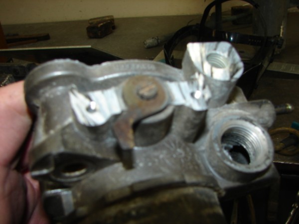 I cut out the aluminum bosses on either side and added a large washer to weld to. Much easier! 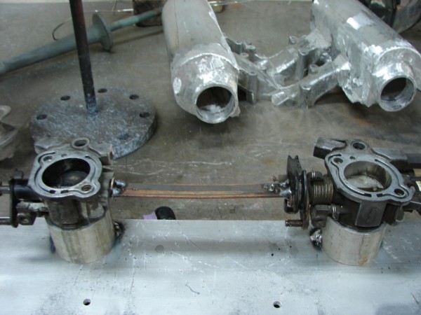 I tacked in a piece of mild steel strap. This is good because it welds up easy, and it the flapper aren't prefectly in synch I can twist the strap a bit to compensate. I actually did this after I finished to get that last 32nd of play out. 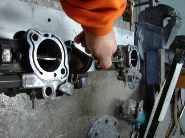 Open, and 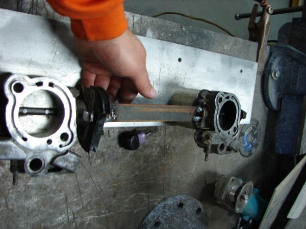 Closed. Now, time to mount them to the real thing 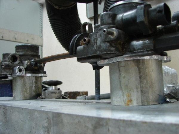 I put the plates I made up under the tbs in the right spots and found that an 11/16 drill closely matches the tb mounting holes. I used this drilll to acurately mark the mounts, then drilled and tapped the plates for 5/16 nf. 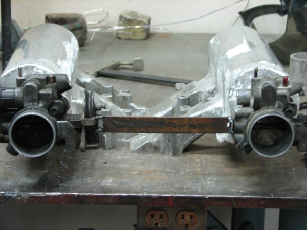 With the plates bolted onto the throttle bodies I spot welded them on to the intake One last WOT shot: 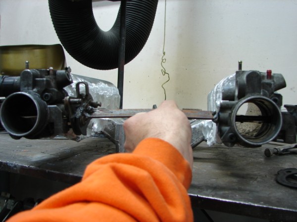 Chay ------------- 86 SE 3.4 |
Posted By: CFoss
Date Posted: 24 March 2010 at 8:47pm
|
Edit, the drill size is 11/32, not 11/16 DOH!
------------- 86 SE 3.4 |
Posted By: Patrick
Date Posted: 25 March 2010 at 12:38pm
|
This looks great, Chay. I'm really hoping you can make it to Vancouver some weekend for a club meeting when you've got this all together!
|
Posted By: CFoss
Date Posted: 26 March 2010 at 8:21am
|
I'd like to come to a meeting. I think it would be fun to give a big presentation on turbo calcs and stuff if people wanted, but I'm not sure when I can get over. Busy busy. I've sort of decided I may as well do the remote ignition module while I'm at it so it will be a while before it's on the road. I just hope after all my dicking around it will still run!
Chay ------------- 86 SE 3.4 |
Posted By: ARTIC-1
Date Posted: 26 March 2010 at 11:11pm
|
Great job on the TB,just wondering about ridgid link between the TB.theres
going to be a little vibration between the two TBs an the welds could fatigue or crack possibly.you could cut the Flat bar in the middle an bolt in a pice of belting or stiff rubber to take out the vibration.just a thought?,any how looks good,hope it all works out well.i see you have tacked the two pipes down to a plate,theres a lot of oxidation on that pipe,witch makes it vary hard to seal weld,just about impossible.iam sure your going to S/S brush it befor you weld,an a little pre heat will make the weld flow real nice to.ive used a ELE hot plate many times,just set the whole thing on the hot plate,turn it on LO/MED-weight 10 min,then weld,makes a big difference the pre heat.any how looks good,can't wate to see the testing. 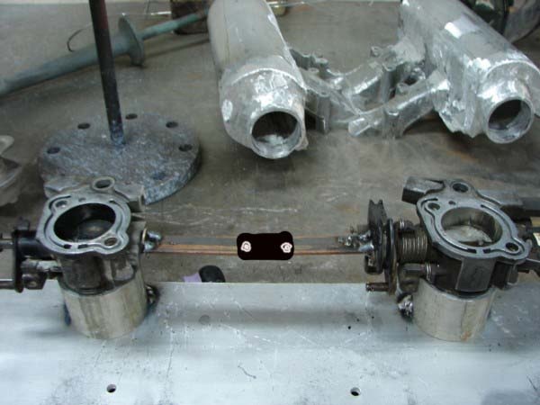 ------------- SNOW MAN 87-GT/AUTO-2.8_ WHITE 88-TTop/ Duke-2.5. RED |