First step toward turbo |
Post Reply 
|
Page <1 45678 19> |
| Author | |
CFoss 
Senior Member 

Joined: 13 February 2007 Location: Canada Status: Offline Points: 580 |
 Post Options Post Options
 Quote Reply Quote Reply
 Posted: 29 March 2010 at 8:34am Posted: 29 March 2010 at 8:34am |
|
Not a bad idea, the stiff rubber.
I'm going to try it first. It's all experimental! There is a bit of longitudinal play in the throttle shafts so I think they will move before there is any stress on the link welds. There will also be thermal expansion forces at work being aluminum so I'll have to watch it and check for binding in all temps/conditions for a while. I'm going to weld it tonight hopefully, so I'll post some pics soon. The batteries died on my dodge cummins this morning, so I have to deal with that too...we'll see.
Thanks for the advice.
Chay Yeah, I'll clean the crap out of the parts. I just wanted to tack it to check allignment and make sure it didn't bind. |
|
|
86 SE 3.4
|
|
 |
|
|
Dawg
Senior Member

Joined: 15 August 2009 Location: Canada Status: Offline Points: 988 |
Post Options
Quote Reply
Posted: 29 March 2010 at 6:57pm |
|
I was also thinking of movement due to heat. Those nacels are going to flex a little when the engine heats them up. This could put a lot of pressure on the throttle plates and cause wear over time. Also there is a real danger that they could get stuck somewhere in rotation. Hopefully not at full throttle....eh? As a bonus, making the linkage in two pieces would make disassembly easier. Just a thought. DG
|
|
|
You dream it up....I'll make it
|
|
|
|
|
CFoss
Senior Member
Joined: 13 February 2007 Location: Canada Status: Offline Points: 580 |
Post Options
Quote Reply
Posted: 07 April 2010 at 8:18pm |
|
I've been thinking about the coupling...I think the movement in the rubber will either be too much in tortion and throw the synch off, or be too stiff and not allow and movement, especially in the longitudinal dimension.
So I've been thinking about a slide coupling...something like cutting link in two, then welding a 3/8 bolt head on one side and a 3/8 socket on the other side. This would be tortionally very stiff, but allow the coupling to slide longitudinally and pivot slightly without affecting synch. Comments? Ideas? Chay |
|
|
86 SE 3.4
|
|
|
|
|
Capt Fiero
Admin Group 

Founding Member Joined: 12 February 2007 Location: Canada Status: Offline Points: 4039 |
Post Options
Quote Reply
Posted: 07 April 2010 at 8:53pm |
|
Tip from Off Road Nuts. Ever heard of a square tube drive shaft. They use 2 pieces of square tube, one that is slightly larger than the other then slide the smaller one inside the larger one. Ideally the outside wall of the smaller one is nearly identical to the inside diameter of the larger one. This allows them to slide back and forth however when rotating, they act as a solid. You can put a thin layer of grease inside to make the action smooth. It is similar to the way a steering coulomb shaft is collapsible. |
|
|
Capt Fiero
88 Fiero GT 5spd V6 Eight Fifty Seven GT V8 5spd. |
|
|
|
|
Dawg
Senior Member
Joined: 15 August 2009 Location: Canada Status: Offline Points: 988 |
Post Options
Quote Reply
Posted: 07 April 2010 at 10:35pm |
|
OK idea, but that sort of linkage might sag and bind because there's not enough overlap. Worth a try though. I would go to a bigger hobby shop. They have various brass and aluminum rounds and tubes. Find a solid round for half of the linkage and a tube for the other. In the solid round, drill a hole near the end of the shaft that will allow a roll pin to fit tightly. This roll pin would have to stick out a bit from one side. Make a slot in the tube that is just wide enough for the roll pin to slide in without binding. Now put the solid round into the tube till the hole lines up with the slot and tap the pin in. Easy? DG
|
|
|
You dream it up....I'll make it
|
|
|
|
|
Patrick
Newbie 
Joined: 19 April 2008 Location: Vancouver Status: Offline Points: 5 |
Post Options
Quote Reply
Posted: 07 April 2010 at 11:24pm |
|
So far, I like Dave's idea the best. (As long as it's possible to acquire two pieces of square tubing the correct size.)
|
|
|
|
|
Dr.Fiero
Senior Post God

Joined: 12 February 2007 Location: Canada Status: Offline Points: 1726 |
Post Options
Quote Reply
Posted: 08 April 2010 at 7:29am |
|
I could draw this better than describing it, but....
---|O|--- A shaft, with a metal 'washer' welded to it. Rubber washer. Another metal 'washer' on another shaft. Each metal washer gets 2 rivets spaced 180* apart attaching it to the rubber. (did that even make sense?!) |
|
|
|
|
CFoss
Senior Member
Joined: 13 February 2007 Location: Canada Status: Offline Points: 580 |
Post Options
Quote Reply
Posted: 08 April 2010 at 1:22pm |
|
I think any of those incarnation would work. It's whatever is easy to source.
I'm not worried about sag in the linkage...they are welded to the throttle body shafts pretty well and that will support them.
I guess ideally there would be a round rod, supports with bearings on either side of the link, and some form of sliding linkage. I need to mock some stuff up and see...
Chay |
|
|
86 SE 3.4
|
|
|
|
|
CFoss
Senior Member
Joined: 13 February 2007 Location: Canada Status: Offline Points: 580 |
Post Options
Quote Reply
Posted: 22 April 2010 at 8:54am |
|
No updates yet, for those watching this thing come to life (ala frankenstein)
I've been busy ripping out the air conditioning condensor, replacing the 4cyl rad with a 6 cyl (I found the 4cyl wasn't up to the job) and replacing the rad fan with one that doesn't groan when it starts up and replacing the rad fan temp switch and testing that out too. Now it all works and is back together (mostly). I had some issues with cooling obviously. I needed to fix these before I fire it up and try to tune the engine. I think I'm going to stick with my orininal idea for the throttle linkage. Perhaps not show quality (Unless I chrome the parts), but very effective.
Chay |
|
|
86 SE 3.4
|
|
|
|
|
CFoss
Senior Member
Joined: 13 February 2007 Location: Canada Status: Offline Points: 580 |
Post Options
Quote Reply
Posted: 24 April 2010 at 3:41pm |
|
I've found that there is too much play between the socket and the bolt to work, so that's out.
I'm worried that if i make the overlapping pipe/pin combo, that when I make it tight enough to keep the synch right that it won't slide very well. So, I found that a universal joint from a steering shaft is really tight, and while a little large, should never break. I'm going to weld to one side of the link shaft to help support it (Rather than in the middle) so I don't get bending but the link can move. I'll post pics when it's done for everyone to laugh at! Chay |
|
|
86 SE 3.4
|
|
|
|
|
Dr.Fiero
Senior Post God
Joined: 12 February 2007 Location: Canada Status: Offline Points: 1726 |
Post Options
Quote Reply
Posted: 24 April 2010 at 3:46pm |
|
Not 100% sure on this, but.... look into some small power tools like a weed eater. They use flexible shafts, and I for some reason think some use very small u-joint like affairs.
|
|
|
|
|
Dawg
Senior Member
Joined: 15 August 2009 Location: Canada Status: Offline Points: 988 |
Post Options
Quote Reply
Posted: 24 April 2010 at 4:18pm |
|
You don't really need a universal. It's the spline portion that you need no?
How about this. Take a piece of square (seemless) tube about 3/16th range. Preferably brass like you can get at the hobby shops. Mate it to a chunk of solid round that you've made square by filing flats in 4 places. You could slowly file away till it fits without jamming. If both pieces were brass it would slide smoothly with just a little light oil. With the right flux you can silver solder brass to steel and it will braze to steel also. DG |
|
|
You dream it up....I'll make it
|
|
|
|
|
CFoss
Senior Member
Joined: 13 February 2007 Location: Canada Status: Offline Points: 580 |
Post Options
Quote Reply
Posted: 24 April 2010 at 9:59pm |
|
The u joint I have is a bit big, but there is no plastic like many of the smaller ones I've seen. I've seen a few weed eaters apart and they had slide splined sections on the power head end of the flex shaft like a driveshaft to tranny coupling, but no unis that I saw. Besides, I don't have any hanging around...I guess I could check out a repair shop for parts.
The slide idea is ok if the expansion/contraction is linear, but will not work if the plenums pivot because this will place of force on the sliding portion of the rod. Sooner or later it will bind. I think this will occur because of the spread nature of the plenums (The angle). That's where the universal has an advantage. Plus, if my throttle bodies are not perfectly alligned (Throttle shafts slightly out of line) the universal is the best way to take up the angle and prevent wear/binding with a 'solid' link. And ok, here's the thing...I kinda like stuff that looks a little funny but works well. I couldn't tell you why. To me the 'perfect' engine bay has been done to death. I like a little home cookin in there. I'll never colour coordinate my ignition leads, that's for sure. But that's just me. Chay |
|
|
86 SE 3.4
|
|
|
|
|
CFoss
Senior Member
Joined: 13 February 2007 Location: Canada Status: Offline Points: 580 |
Post Options
Quote Reply
Posted: 30 April 2010 at 11:21am |
|
Ok, I had what I think is a good idea.
Seeing as I used a piece of flat steel for my linkage, to keep things simple, I'm going to cut a gap in it, then sleeve it with a sleeve a bit taller than the original flat steel piece. This serves three purposes: 1) The 1" flat makes it easier to get a small rotational error because the sleeve can be pretty tight and still slide longitudinally vs a pin and groove idea 2) The increased height of the sleeve (small vertical gap) will allow for slight pivoting in the throttle body shafts 3) The length of the sleeve will contribute to it's stiffness (It won't sag) To service a throttle body, the shaft would just slide out of the sleeve. What do you think? It seems to conform to the KISS principal anyway. It may be hard to visualize based on what I've written. The sleeve would be 2 pieces of flat steel about 2-3 inches long with a gap in between them. I'll weld a top and a bottom onto them. So they sandwich the original linkage. Chay |
|
|
86 SE 3.4
|
|
|
|
|
CFoss
Senior Member
Joined: 13 February 2007 Location: Canada Status: Offline Points: 580 |
Post Options
Quote Reply
Posted: 02 May 2010 at 3:49pm |
|
I did some more today. Basically I welded on the end plates and fabbed up some port connections for the MAP sensor and the brake booster:
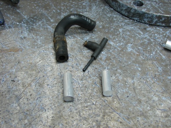 Above is the brake booser hose connection and the MAP connection. I took some round 1/2 inch stock pieces and mill them down with the help of a drill press and a file. 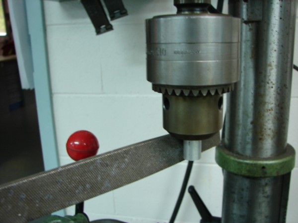 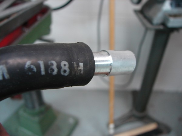 Here's the booster hose one 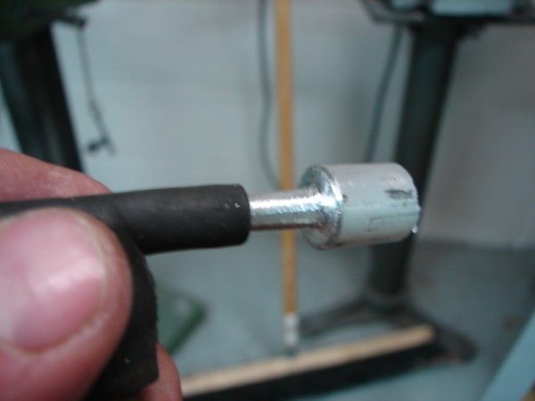 And the MAP one. I drilled each of them at this point. 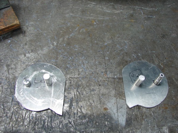 Here they are layed out on the end plates. The other 2 will be drilled out for the balance tube to connect to. I welded at this point. Then I drilled through the plates all too. 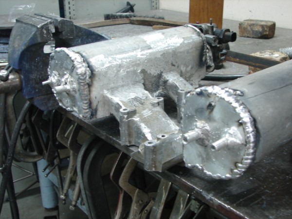 Final pic. Now, for the throttle cable bracket and linkage coupler... Chay |
|
|
86 SE 3.4
|
|
|
|
|
CFoss
Senior Member
Joined: 13 February 2007 Location: Canada Status: Offline Points: 580 |
Post Options
Quote Reply
Posted: 02 May 2010 at 7:36pm |
|
Oops, looks like I need one more for the PCV system...
A little more time on the file I think. C |
|
|
86 SE 3.4
|
|
|
|
|
CFoss
Senior Member
Joined: 13 February 2007 Location: Canada Status: Offline Points: 580 |
Post Options
Quote Reply
Posted: 03 May 2010 at 9:46pm |
|
And ok, here's the thing...I kinda like stuff that looks a little funny
but works well. I couldn't tell you why. To me the 'perfect' engine bay
has been done to death. I like a little home cookin in there. I'll never
colour coordinate my ignition leads, that's for sure.
But that's just me. I did just repaint my valve covers though....silver for a bit of bling (I mean, to prevent them from corroding  ). ).I guess I`m not immune. Chay |
|
|
86 SE 3.4
|
|
|
|
|
CFoss
Senior Member
Joined: 13 February 2007 Location: Canada Status: Offline Points: 580 |
Post Options
Quote Reply
Posted: 16 May 2010 at 8:29pm |
|
I finished the throttle linkage and it works great. It slides around but is rotationally tight.
I also just pressure tested my manifold. It took a while to make gaskets for the throttle bodies and bottom plates but they held ok. I need to fix up 6-7 leaks, a couple biggies, but mostly really small, so I'm happy about that. The big ones are in placed you'd expect once you know where they are. I figure I'll weld the big ones up and epoxy the little ones. No time for pics today, but soon... Chay |
|
|
86 SE 3.4
|
|
|
|
|
Romeo
Senior Post God

Joined: 16 November 2008 Location: Canada Status: Offline Points: 3033 |
Post Options
Quote Reply
Posted: 16 May 2010 at 11:04pm |
|
Sick brother. Be sure to snap those pictures soon, I'm curious to see the results.

|
|
|
Never shift into reverse without a back-up plan.
|
|
|
|
|
CFoss
Senior Member
Joined: 13 February 2007 Location: Canada Status: Offline Points: 580 |
Post Options
Quote Reply
Posted: 24 May 2010 at 7:01pm |
|
A couple more pics:
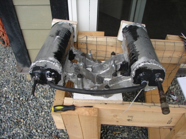 This is the manifold now...looks a bit different with the epoxy on it. I had a bunch of pinholes so I went a bit crazy on it. I used this stuff: 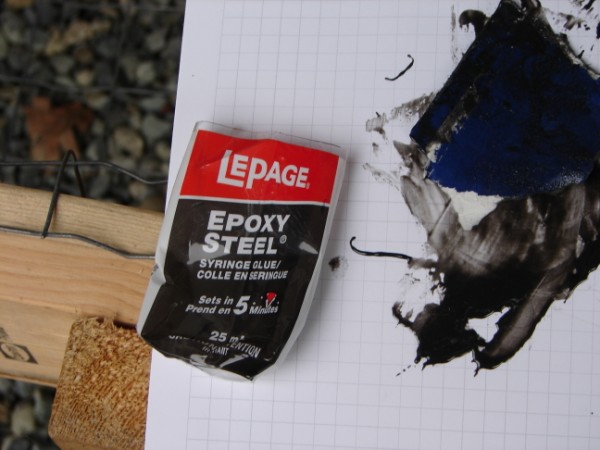 I hardens very hard. I hope it lasts. We'll see! 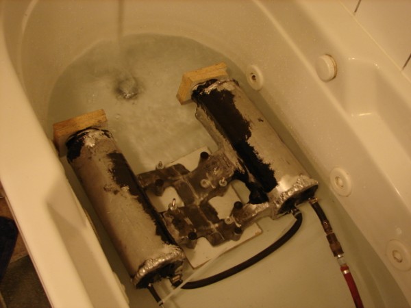 Rub a dub dub. No bubbles (Sweet!). Chay |
|
|
86 SE 3.4
|
|
|
|
|
Post Reply
|
Page <1 45678 19> |
 Tweet
Tweet
|
| Forum Jump | Forum Permissions You cannot post new topics in this forum You cannot reply to topics in this forum You cannot delete your posts in this forum You cannot edit your posts in this forum You cannot create polls in this forum You cannot vote in polls in this forum |


 Topic Options
 ARTIC-1 wrote: