First step toward turbo |
Post Reply 
|
Page <12345 19> |
| Author | ||||||||||||||||||||||||||||||
Patrick 
Newbie 
Joined: 19 April 2008 Location: Vancouver Status: Offline Points: 5 |
 Post Options Post Options
 Quote Reply Quote Reply
 Posted: 15 January 2010 at 11:24pm Posted: 15 January 2010 at 11:24pm |
|||||||||||||||||||||||||||||
|
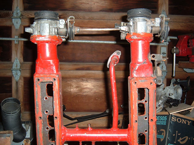
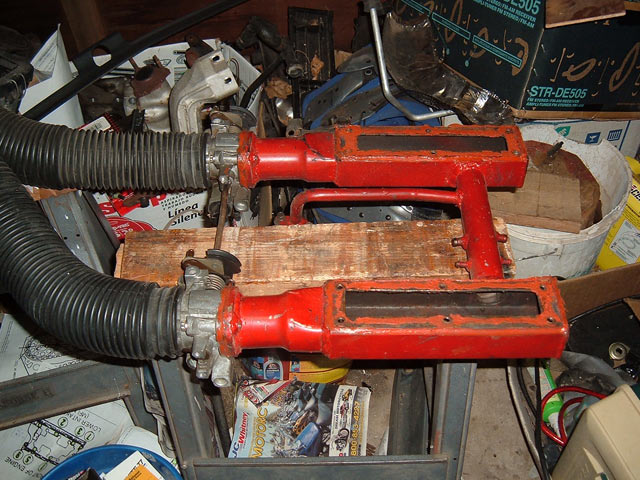
Hey Chay, looks like you're having some fun there! I'm just curious, what was your reason for cutting the runners as oppossed to mounting the tubes on the ends of the original runners? I'm not suggesting you should or shouldn't have, I'm just wondering why you chose the path you did? Here's a couple of images of a dual-plenum manifold I almost bought from the Mall at Pennock's over a year ago. I eventually decided against it for three reasons... 1) More trouble than I needed. 2) Made of steel and heavy. 3) Ugly as sin.
|
||||||||||||||||||||||||||||||
 |
||||||||||||||||||||||||||||||
|
CFoss
Senior Member 

Joined: 13 February 2007 Location: Canada Status: Offline Points: 580 |
Post Options
Quote Reply
Posted: 16 January 2010 at 2:17pm |
|||||||||||||||||||||||||||||
|
There is a thread in pennocks that I got this from...there are a bunch of guys with cut down runners. They say they are getting better low and top end performance.
I don't know too much about design on intakes, but I suspect the low end performance comes in the decreased resonance point because of the shortened runners, and the top end because of removing the obstruction in the upper intake allows more total airflow. Also, there is a height issue if it gets too tall. And cutting the middle eliminates one 90deg ish turn the air has to make in the middle plenum. That was the long answer. The short one is someone did it before and had success, so i don't want to reinvent the wheel. As for the above...totally agree! Chay |
||||||||||||||||||||||||||||||
|
86 SE 3.4
|
||||||||||||||||||||||||||||||
|
||||||||||||||||||||||||||||||
|
Dr.Fiero
Senior Post God 

Joined: 12 February 2007 Location: Canada Status: Offline Points: 1726 |
Post Options
Quote Reply
Posted: 16 January 2010 at 3:17pm |
|||||||||||||||||||||||||||||
The guy who makes the Trueleo intake used to make both a short and long runner version. He discontinued the long runner version, saying that the short length one outsold the long, and had pretty much the same performance overall, with way more in the bottom where most people run anyhow. So.... Short is good. |
||||||||||||||||||||||||||||||
|
||||||||||||||||||||||||||||||
|
Patrick
Newbie
Joined: 19 April 2008 Location: Vancouver Status: Offline Points: 5 |
Post Options
Quote Reply
Posted: 16 January 2010 at 6:59pm |
|||||||||||||||||||||||||||||
|
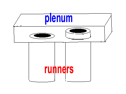
Chay, I don't remember the name given to this technique/addition, but had you looked into adding "extensions" to the runner tubes where they enter the plenum? They stick up a bit from the floor of the plenum. It's supposed to help flow. Do you know what I'm talking about? Okay, don't laugh... I tried to draw it for you. The runner with the extension thingy is on the right. The shape isn't right, but it should be good enough to get the idea across.
Keep in mind I was only wondering why Chay cut the last inch or so off the runners.
|
||||||||||||||||||||||||||||||
|
||||||||||||||||||||||||||||||
|
CFoss
Senior Member
Joined: 13 February 2007 Location: Canada Status: Offline Points: 580 |
Post Options
Quote Reply
Posted: 17 January 2010 at 10:52am |
|||||||||||||||||||||||||||||
|
They are called velocity stacks, I saw them in another professionally done intake. I hadn't considered it, but it actually might be easy to do...just clean up the runners for the thickness of my pipes plus a bit more, and enlarge the holes in the pipes to accept a bit of the runners into them. Then I don't have to be so carefull to match the ports too, and weld the outside of the connection.
I'd like to research it some more...it's curious how it would increase flow. Like I said I have seen it so I'm a believer....just want to know how it works. Chay |
||||||||||||||||||||||||||||||
|
86 SE 3.4
|
||||||||||||||||||||||||||||||
|
||||||||||||||||||||||||||||||
|
CFoss
Senior Member
Joined: 13 February 2007 Location: Canada Status: Offline Points: 580 |
Post Options
Quote Reply
Posted: 17 January 2010 at 10:53am |
|||||||||||||||||||||||||||||
|
I made note of the discontinued Truleo...when all arrow point in the same direction it makes decisions like that easier.
C |
||||||||||||||||||||||||||||||
|
86 SE 3.4
|
||||||||||||||||||||||||||||||
|
||||||||||||||||||||||||||||||
|
Patrick
Newbie
Joined: 19 April 2008 Location: Vancouver Status: Offline Points: 5 |
Post Options
Quote Reply
Posted: 17 January 2010 at 11:00am |
|||||||||||||||||||||||||||||
|
Hey, now you're talking. Sounds great! Keep in mind they need to be trumpet shaped.
Yes, "velocity stacks". That's the term I couldn't remember.
|
||||||||||||||||||||||||||||||
|
||||||||||||||||||||||||||||||
|
CFoss
Senior Member
Joined: 13 February 2007 Location: Canada Status: Offline Points: 580 |
Post Options
Quote Reply
Posted: 17 January 2010 at 11:01am |
|||||||||||||||||||||||||||||
|
Looks like all the pro velocity stacks have a bevel on the inside...so I'll bevel the runners before I weld them into the plenum and it should accomplish the same thing. Good tip.
Chay |
||||||||||||||||||||||||||||||
|
86 SE 3.4
|
||||||||||||||||||||||||||||||
|
||||||||||||||||||||||||||||||
|
CFoss
Senior Member
Joined: 13 February 2007 Location: Canada Status: Offline Points: 580 |
Post Options
Quote Reply
Posted: 17 January 2010 at 3:16pm |
|||||||||||||||||||||||||||||
|
I think the ones in the middle of your pic are what I'll try to d. Not too proud, but enough to try the bevel.
Now, is that curve eliptical or logaritmic? Ha ha. I wish I could get an eliptical dremmel. Chay |
||||||||||||||||||||||||||||||
|
86 SE 3.4
|
||||||||||||||||||||||||||||||
|
||||||||||||||||||||||||||||||
|
CFoss
Senior Member
Joined: 13 February 2007 Location: Canada Status: Offline Points: 580 |
Post Options
Quote Reply
Posted: 17 January 2010 at 8:55pm |
|||||||||||||||||||||||||||||
|
Ok, for injectors...here we go...
There are two measurements which are important. The grove to top height and the grove to bottom height. Then, there is the flow, in CC or in pounds/hour. 500cc is about 49 lb/hr, so you can convert. Also, there is the injector impedance to consider. First, the group of injectors I'm messing with: 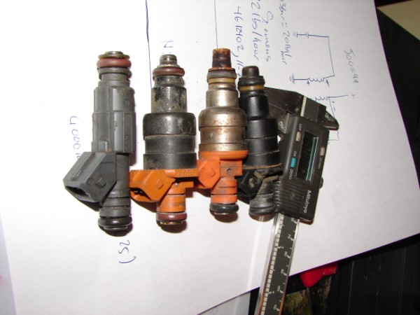 How did these get upside down??? Ha ha. The left is a LT1 injector(24lb/hr)...I cut the top groove, the bottom is stock for reasons you will see below. The second is a 1996 3.8L dodge injector(22 or 24#/hr), a Siemens Deka 666A. the third is a 1996 3.0l dodge injector, a nippondenso INP-066 (19 OR 20#/HR) and the last is the Fiero stocker (14#/hr). More on the stockers... 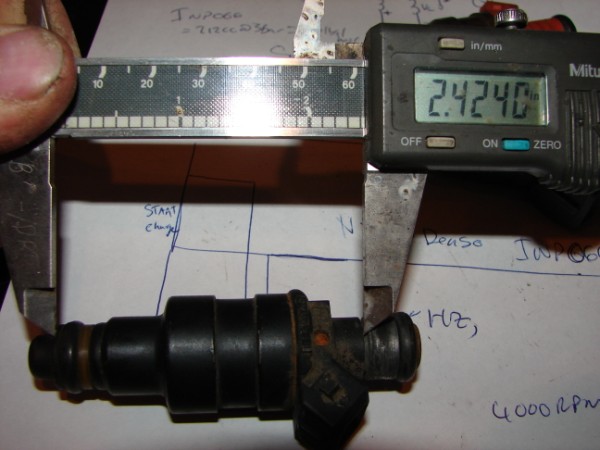 2.42 is the body length, and is critical because this is the distance between the fuel rail and the lower manifold. If this isn't right there is a good chance you will have vaccuum leaks and it won't seat in the lower manifold far enough for a good injection into the air path. 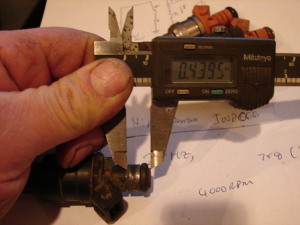 This is the ring groove to top measure on the stocker. this will fully insert the top on the injector into the rail. The port is cylindrical to the end where there is a small bevel to ease insertion into the rail. as long as the o-ring is past the bevel, there is no difference in sealing from there on up. This allows a smaller groove to top dimension to be used, which allows many injectors to interchange. Nipondenso (19-20#/hr): 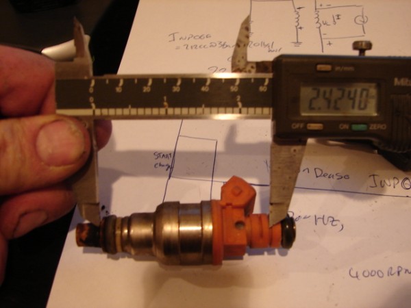 The body height is the same so this is a good candidate. How is the groove to top height? 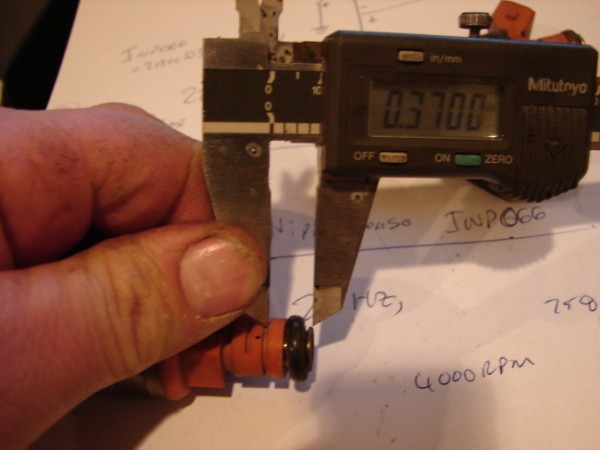 At .37, it's smaller than stock (.43), but should still easily seal. This is my fall back set of injectors. They are high Z so no problem with the ecm. Siemens Deka (24#/hr): 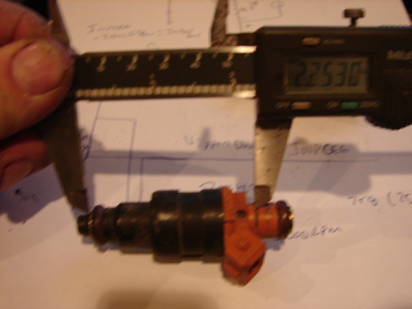 2.25", uh-oh. It's a no go. Too bad, the #/hr is what I'm after. Ok, LT1 injectos (GM 2561462, Bosch 280 155 931) at 24#/hr. These are rated at 28#/hr, but at higher pressure, so they are at about 24#/hr where I want to run (44psi or so). 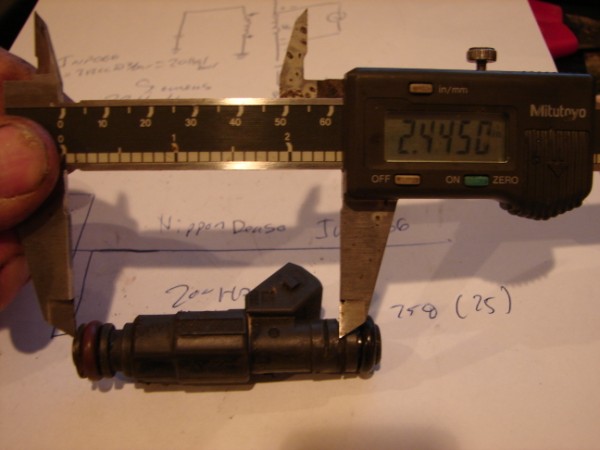 You can see the original groove (Lower) and the groove I made. From the groove I made the body length is perfect (.02" difference, no big deal). So how is the g-top measure... 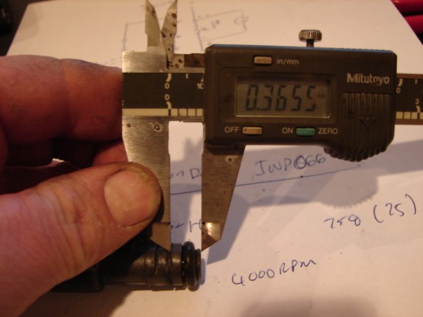 .36, not bad, not super good. It will seal though. It's a very similar measure to the nippondenso. Here is a few shots of the rail and lower manifold: 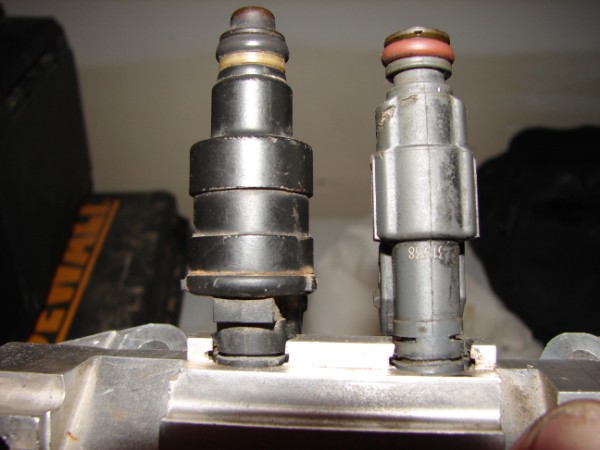 Stock vs LT1 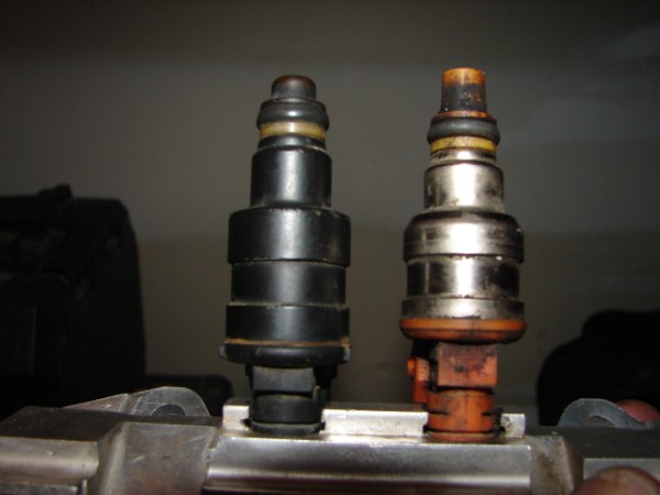 Stock vs nippondenso 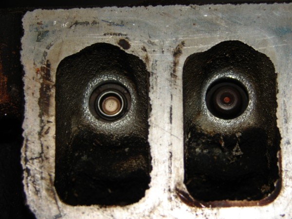 LT1 vs stock 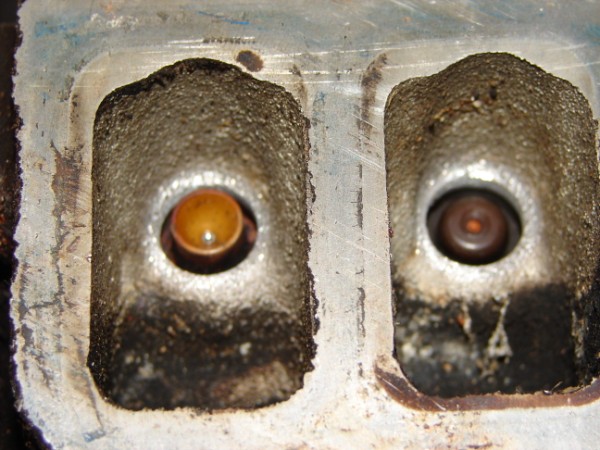 Nippondenso vs stock 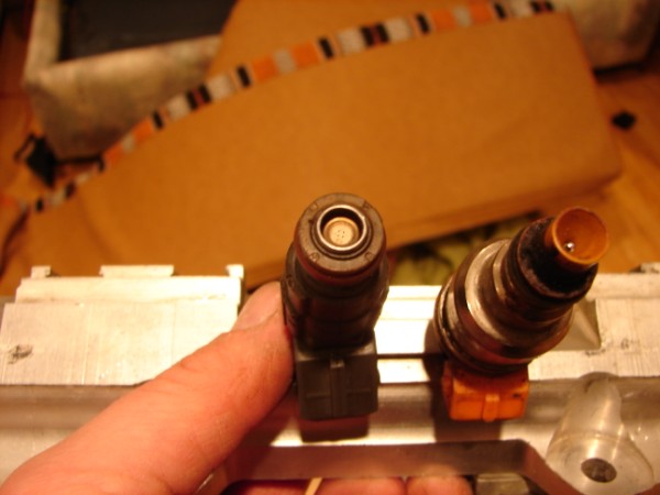 LT1 (disk pattern) vs nippindenso pintle Chay |
||||||||||||||||||||||||||||||
|
86 SE 3.4
|
||||||||||||||||||||||||||||||
|
||||||||||||||||||||||||||||||
|
Patrick
Newbie
Joined: 19 April 2008 Location: Vancouver Status: Offline Points: 5 |
Post Options
Quote Reply
Posted: 18 January 2010 at 11:35am |
|||||||||||||||||||||||||||||
|
Thanks Chay, I hope it yields you a few extra ponies. Someday you'll have to make it across the pond to a club function so we can all meet you and your Fiero.
|
||||||||||||||||||||||||||||||
|
||||||||||||||||||||||||||||||
|
CFoss
Senior Member
Joined: 13 February 2007 Location: Canada Status: Offline Points: 580 |
Post Options
Quote Reply
Posted: 18 January 2010 at 8:27pm |
|||||||||||||||||||||||||||||
|
One day.
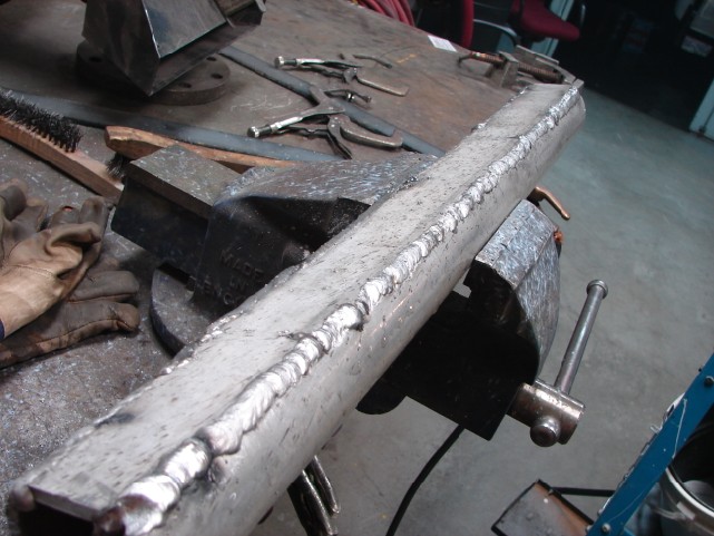
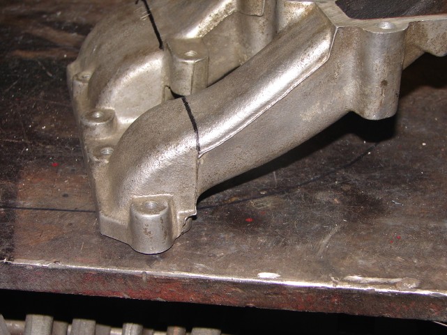
When I was over there I never made it though. Too much family commitments. I did up the runners, as best I could. The pics don't really do it justice, but: 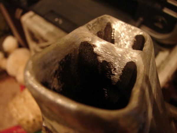 Sort of trumpetty....I made sure the corners were very rounded and smooth. 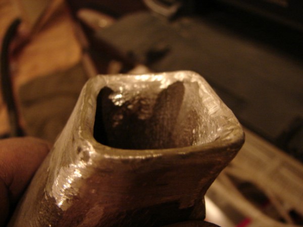 Will it work? Who knows. Chay |
||||||||||||||||||||||||||||||
|
86 SE 3.4
|
||||||||||||||||||||||||||||||
|
||||||||||||||||||||||||||||||
|
Patrick
Newbie
Joined: 19 April 2008 Location: Vancouver Status: Offline Points: 5 |
Post Options
Quote Reply
Posted: 18 January 2010 at 8:38pm |
|||||||||||||||||||||||||||||
|
If it doesn't work, you've only lost a bit of time. If it does work, I want at least half the credit.
|
||||||||||||||||||||||||||||||
|
||||||||||||||||||||||||||||||
|
Capt Fiero
Admin Group

Founding Member Joined: 12 February 2007 Location: Canada Status: Offline Points: 4039 |
Post Options
Quote Reply
Posted: 18 January 2010 at 10:16pm |
|||||||||||||||||||||||||||||
|
Flow-bench numbers for Stock intake and SR14 & LR17 below.
|
||||||||||||||||||||||||||||||
|
Capt Fiero
88 Fiero GT 5spd V6 Eight Fifty Seven GT V8 5spd. |
||||||||||||||||||||||||||||||
|
||||||||||||||||||||||||||||||
|
CFoss
Senior Member
Joined: 13 February 2007 Location: Canada Status: Offline Points: 580 |
Post Options
Quote Reply
Posted: 19 January 2010 at 10:57am |
|||||||||||||||||||||||||||||
|
Yeah, the numbers are hard for me to put into real world practical terms. What I'd like to know is at 5500 rpm, what is the difference in flow? I have a 3.4, with a higher lift cam. It stands to reason that this combo will benefit more from a free flowing intake than a stock 2.8. I definately run out of air before 5k. It's quite annoying.
Anyway look at these stacks: 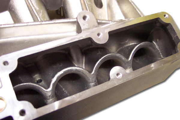 They look a lot bigger than what I'm making. I think what I might do is redo the plenum. This time I'll cut the holes to accept the runners in the flat plate, then insert the runners and weld tabs on the runners to create a horn style velocity stack (Think like a tweeter horn in reverse). Then weld the runners to the flat plate, and finally the flat plate to the tubular material. It would be more effective that way i think. Chay |
||||||||||||||||||||||||||||||
|
86 SE 3.4
|
||||||||||||||||||||||||||||||
|
||||||||||||||||||||||||||||||
|
CFoss
Senior Member
Joined: 13 February 2007 Location: Canada Status: Offline Points: 580 |
Post Options
Quote Reply
Posted: 19 January 2010 at 7:14pm |
|||||||||||||||||||||||||||||
|
After doing a bit more research I found lots of V stack pics. They have bigger and more circular radiuses, but mine will work somewhat. It's better than not doing the shaping for sure.
With our oval and disimilar shaped runners it will be hard to get anything comercial to fit, so shaping the oem seems to me the best solution to keep it simple. May of the V stacks don't extend that far into the plenum, so I'm going to try 1/4-1/2 inch. Chay |
||||||||||||||||||||||||||||||
|
86 SE 3.4
|
||||||||||||||||||||||||||||||
|
||||||||||||||||||||||||||||||
|
Patrick
Newbie
Joined: 19 April 2008 Location: Vancouver Status: Offline Points: 5 |
Post Options
Quote Reply
Posted: 19 January 2010 at 10:24pm |
|||||||||||||||||||||||||||||
|
I think that's a great idea. Will you be fabricating a balance tube between the two plenums?
|
||||||||||||||||||||||||||||||
|
||||||||||||||||||||||||||||||
|
CFoss
Senior Member
Joined: 13 February 2007 Location: Canada Status: Offline Points: 580 |
Post Options
Quote Reply
Posted: 21 January 2010 at 9:29am |
|||||||||||||||||||||||||||||
|
The shape of the plenum will be the same, it's just that it will be assembled in a way where I can work the interior. It's a space issue on the top of the engine. Too big a diameter and the trunk lid will hit.
I think the size is adequate: 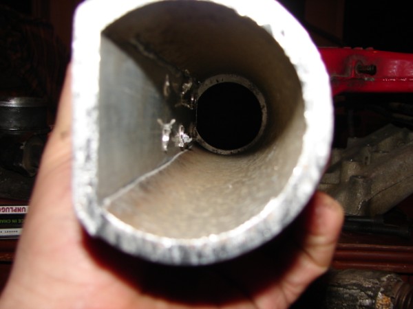 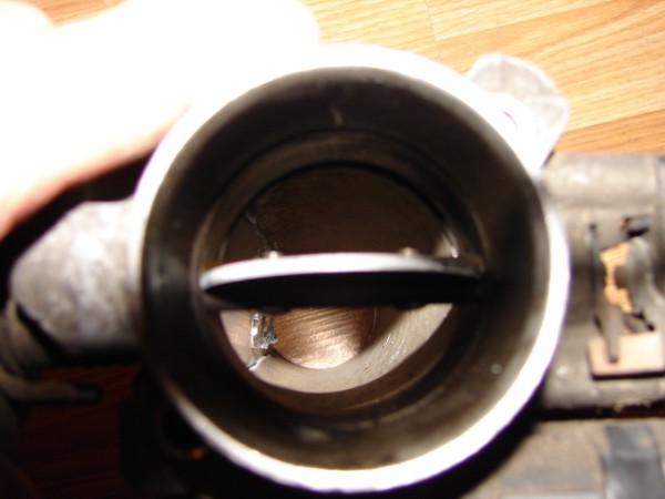 As you can see the throttle body fits ok (It's big enough). The junk in the interior is from drilling the corners of the runner entrances. This time I will start with doing the flat piece. I will cut out the runner entrances and then insert the runners, tack it in place and then build the horns on the 'inside', the to finish it, weld on the tube section. This will help 2 fold: 1) The runners enter at an angle, so I can weld to fill the gap left by the angle on the inside 2) I can build better V stacks because I can make them bigger and shape them better, and have access to machine them This is what I have in mind as a model (It's a bit fuzzy). 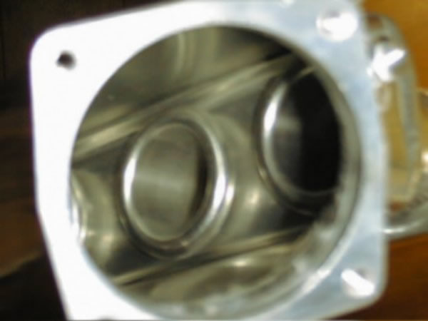 It'll end up somewhat different (More horn type than trumpet type), but that's the idea. Chay |
||||||||||||||||||||||||||||||
|
86 SE 3.4
|
||||||||||||||||||||||||||||||
|
||||||||||||||||||||||||||||||
|
CFoss
Senior Member
Joined: 13 February 2007 Location: Canada Status: Offline Points: 580 |
Post Options
Quote Reply
Posted: 21 January 2010 at 9:31am |
|||||||||||||||||||||||||||||
|
Yeah, I'm going to do a 1" balance tube, but I want to mock it up on the engine before deciding where it's going. There are some other provisions as well, like egr (I think I'll delete it) and map sensor, brake vaccuum source etc.
Chay |
||||||||||||||||||||||||||||||
|
86 SE 3.4
|
||||||||||||||||||||||||||||||
|
||||||||||||||||||||||||||||||
|
CFoss
Senior Member
Joined: 13 February 2007 Location: Canada Status: Offline Points: 580 |
Post Options
Quote Reply
Posted: 21 January 2010 at 9:35am |
|||||||||||||||||||||||||||||
|
||||||||||||||||||||||||||||||
|
Post Reply
|
Page <12345 19> |
 Tweet
Tweet
|
| Forum Jump | Forum Permissions You cannot post new topics in this forum You cannot reply to topics in this forum You cannot delete your posts in this forum You cannot edit your posts in this forum You cannot create polls in this forum You cannot vote in polls in this forum |


 Topic Options
 CFoss wrote:


 I was disappointed when you posted the image below because I felt you had severely limited yourself with what you could do with the plenum. Doing it over again in the manner mentioned above will give you ample opportunity to do a much better job.